


- Coaxial Capillary Microfluidic Chips Modified with Poly(vinyl alcohol) for the Long-term Production of Uniform Oil Droplets
Guk-Young Ahn*, **,# , Inseong Choi*, **,# , Se Hee Hwang*, **, Jong Hwa Seo*, **, Eun Seo Kim*, **, Do-Hyun Oh*, **, Young-Hyun Ryu*, **, Min-Ho Kang*, **,†
 , and Sung-Wook Choi*, **,†
 *Biomedical and Chemical Engineering, The Catholic University of Korea, 43 Jibong-ro, Wonmi-gu, Bucheon-si, Gyeonggi-do 14662, Korea
**Department of Biotechnology, The Catholic University of Korea, 43 Jibong-ro, Wonmi-gu, Bucheon-si, Gyeonggi-do 14662, Korea- 균일한 에멀젼의 연속 생산을 위해 폴리비닐 알코올로 개질한 동축 정렬 캐필러리 미세유체장치
안국영*, **,# · 최인성*, **,# · 황세희*, ** · 서종화*, ** · 김은서*, ** · 오도현*, ** · 류영현*, ** · 강민호*, **,†
· 최성욱*, **,† *가톨릭대학교 바이오메디컬화학공학과, **가톨릭대학교 생명공학과
Reproduction, stored in a retrieval system, or transmitted in any form of any part of this publication is permitted only by written permission from the Polymer Society of Korea.
Coaxially aligned microfluidic devices were fabricated using a round silica microcapillary and a square glass capillary with different inner diameters (200 and 300 µm). The inner wall of the square glass capillary was modified with poly(vinyl alcohol) (PVA) through plasma treatment to provide a hydrophilic surface. The microfluidic device consisting of the glass capillary with the smaller inner diameter demonstrated uniform oil droplet formation, compared to that with the larger inner diameter. The production of uniform droplets and microspheres originated from the coaxial alignment of the silica microcapillary with the square glass capillary. The glass substrate treated by plasma and PVA modification exhibited a hydrophilic surface, resulting in more stable uniform droplet formation for 6 h. The microfluidic device with PVA-coated glass capillary can be potentially used as a platform for the reproducible and reliable production of uniform oil droplets for a long period of time.
50 μm의 내경과 150 μm의 외경을 갖는 원형 실리카 캐필러리와 200 혹은 300 μm의 내경을 갖는 정사각형 유리 캐필러리를 사용하여 동축으로 정렬된 미세유체장치를 제작하였다. 실리카 캐필러리와 유리 캐필러리의 동축 정렬이 200 μm의 내경을 갖는 유리 캐필러리에서 더 유리하였으며, 300 μm 내경 보다 균일한 에멀젼 형성이 가능하였다. 장시간 에멀젼 형성 실험에서 폴리비닐 알코올로 친수성 개질된 유리 캐필러리를 사용할 경우 6시간 동안 안정적이고 균일한 에멀젼 형성이 가능하였다. 본 연구에서 제조한 폴리비닐 알코올로 표면 개질된 유리 캐필러리와 실리카 캐필러리를 이용한 미세유체장치는 장시간 동안 균일한 에멀젼을 제조하기 위한 플랫폼으로 활용될 수 있다.
We fabricated a coaxially aligned microfluidic device by inserting a round-shaped silica microcapillary into a square glass capillary with different inner diameters of 200 and 300 ¥ìm. The inner wall of the square glass capillary was modified with poly(vinyl alcohol) (PVA) through plasma treatment. The microfluidic device prevented the flow along the wall of the glass capillary tube, resulting in the production of uniform droplets in a reproducible manner.
Keywords: silica capillary, square capillary, microfluidic device, emulsion, modification.
This study was supported by the National Research Foundation of Korea (NRF) grant funded by the Korean government (MIST) (No. 2021R1A2C1003865) Korea Drug Development Fund funded by the Ministry of Science and ICT, Ministry of Trade, Industry, and Energy, and Ministry of Health and Welfare (HN21C0317, Republic of Korea), and the Advanced Technology Center plus (20017970, Development of domestic microfluidic devices and real time process analysis technology for more than 10 g/h of medicine production) funded by the Ministry of Trade, Industry & Energy (MOTIE, Korea).
The authors declare that there is no conflict of interest.
Microfluidics has been proved to be an important platform technology in a variety of research fields, such as biology, chemistry, physics, electronics, and medicine.1-5 The unique advantages of the microfluidic approach are reductions in operation system, reagent amount, and required energy, as well as design flexibility and portability.6,7 Thanks to those benefits, the microfluidic application field has been expanding to chemical reaction, cell-based assay, biological analysis, organ-on-a-chip, etc. Many types of materials have been used for the fabrication of microfluidic devices, including poly(dimethylsiloxane), glass, wafer, and polymer.8-11 Despite wide popularity, those materials have the critical drawback of limited hydrophilicity. Therefore, many methods were developed to modify the inner wall of the microchannels in microfluidic devices. Plasma treatment and subsequent silanization was the most often used technique for the surface modification. The surface property of the microchannels was controlled by the type and amount of the silanes in a relatively simple way. Chemical vapor deposition, layer-by-layer coating, and polymer grafting methods were also utilized to improve the hydrophilicity of the microchannels. However, most methods were limited in terms of the long-term reliability for droplet generation.12
Among many applications, the microfluidic production of a uniform emulsion for drug delivery systems can be considered an application that is close to industrialization. However, unstable jetting flow behavior and undesirable microchannel clogging in the microfluidic device are major issues for the reliable and reproducible production of uniform emulsions.13,14 Microchannel design and surface modification should be properly conducted to address these issues. For example, coaxial alignment of the microchannels is necessary for stable droplet formation in a capillary-based microfluidic approach. In addition, the surface of the microchannel should be modified by considering the chemical and physical properties of the fluid to flow. Much research has been conducted on the surface modification procedure to change the hydrophilicity of the microchannels.15 Besides plasma treatment, various hydrophilic molecules, such as silanes, dopamine, polysaccharides, polyethylene glycol, and poly(vinyl alcohol), were modified onto the surface of the microchannels through physical adsorption/coating and chemical coupling/grafting.16-20
In this work, we fabricated a simple microfluidic device by inserting a silica microcapillary into a square glass capillary. The outer diameter of the silica capillary was slightly less than the inner diameter of the glass capillary, facilitating coaxial alignment of the capillaries. The droplet formation behavior at the tip of the silica microcapillary was monitored to ensure long-term reliability and reproducibility. In addition, the inner wall of the glass capillary was modified by poly(vinyl alcohol) (PVA) through plasma treatment and baking method. The microfluidic device with the PVA-modified glass capillary demonstrated more stable droplet formation for longer time. We believe that the microfluidic device with coaxial alignment and PVA-modified surface can be a platform for the stable and continuous production of uniform emulsion droplets.
Materials. Poly(vinyl alcohol) (PVA, Sigma–Aldrich) was used to modify the inner surface of the square glass capillary, as well as for the surfactant for the continuous phase. Poly(L-lactic acid) (PLA, Resomer LR 704 S, Evonik) was used as the polymer for the microspheres. Oil Red O (Aldrich) was used as a hydrophobic dye for the oil phase. Dichloromethane (DCM, Sigma–Aldrich) served as an organic solvent for PLA. Fused silica microcapillary (50 μm I.D. × 150 μm O.D.) was purchased from Polymicro Technologies (Phoenix, AZ, USA). Square glass capillaries with different inner diameters of 200 and 300 μm were purchased from Vitro Tubes (Mountain Lakes, NJ, USA).
Fabrication of the Microfluidic Device. A silica microcapillary (5 cm in length) was inserted into a square glass capillary and placed on slide glass. The silica capillary (inlet for the discontinuous phase) was inserted into a 24G needle, followed by sealing with an epoxy adhesive. The 18G needle was placed at the part where the glass capillary and the silica capillary were inserted, then fixed using an epoxy adhesive. The 18G needle connected with Tygon® tube (1/32 in I.D. × 3/32 in O.D.) was used as an inlet for the continuous phase.
PVA Modification. A slide glass was treated with plasma (PDC-32G-2, Harrick plasma Inc., USA) for 90 s and then an aqueous solution (1 wt%) of PVA (Mw 13000-23000) was dropped onto the surface of the plasma-treated slide glass, followed by baking in an oven for 30 min at 110 ℃. The contact angle was analyzed after washing the slide glass with hot water (70 ℃) for 30 min. The PVA modification of the inner wall of a square glass capillary was conducted by soaking the square glass capillary in the aqueous PVA solution after plasma treatment under the same condition for the slide glass.
Production of PLA Microspheres. PLA solution (1 wt%) in DCM and an aqueous phase with PVA (2 wt%) were used as the discontinuous and continuous phases, respectively. Both phases were introduced into the microfluidic device by syringe pumps (NE-1000, New Era Pump Systems Inc., USA). The flow rates for the continuous phase varied from 0.2 to 2.0 mL/min, while the flow rate of the discontinuous phase was fixed at 0.02 mL/min. The resultant oil droplets from the microfluidic device with different square capillaries were collected on a concave glass and analyzed by optical microscopy (BX-43, Olympus, Japan). The average sizes of the droplets and corresponding microspheres were calculated using ImageJ® (National Institutes of Health, USA) (n = 100). The coefficient of variation (CV) was calculated from the ratio of the standard deviation to the average value. Droplet formation at the tip of the silica capillary was observed by digital microscopy (DM0205, Boli Optics, USA) to obtain time-lapse images.
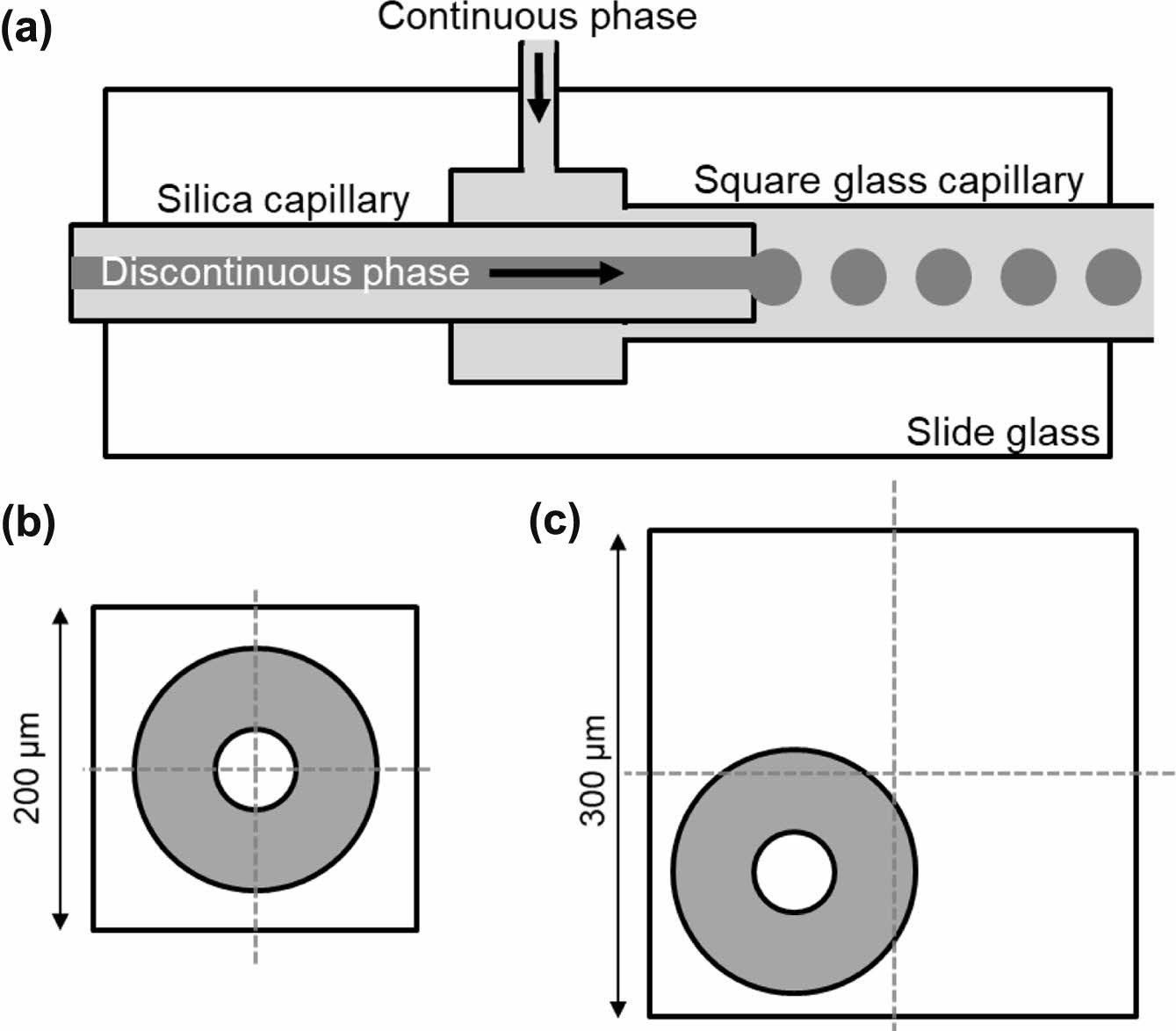
Figure 1(a) shows a schematic of the simple capillary-based microfluidic device. The microfluidic device with two channels was fabricated by inserting a round-shape silica microcapillary into a rectangular glass capillary. The silica microcapillary had an inner diameter of 50 μm and an outer diameter of 150 μm. Glass capillaries with a slightly larger diameter (200 and 300 μm) than the outer diameter of the silica microcapillary were used to investigate the effect of coaxial alignment on droplet formation behavior. The discontinuous and continuous phases were introduced through the silica microcapillary and glass capillary, respectively, using two syringe pumps. The continuous phase flew through the space between the silica microcapillary and the glass capillary in the microfluidic device. The discontinuous phase was pinched off at the end of the silica microcapillary, resulting in oil droplets. Figure 1(b) and 1(c) show schematic cross-sectional views of the microfluidic device consisting of the silica microcapillary within the rectangular glass capillary. As shown in Figure 1(b), the axis of the silica capillary was placed at nearly the center of the glass capillary with inner diameter of 200 μm, due to the small gap (50 μm) between the outer diameter of the silica microcapillary and the inner diameter of the glass capillary. However, it was hard to align the axis of the silica microcapillary at the center of the glass capillary with inner diameter of 300 μm.
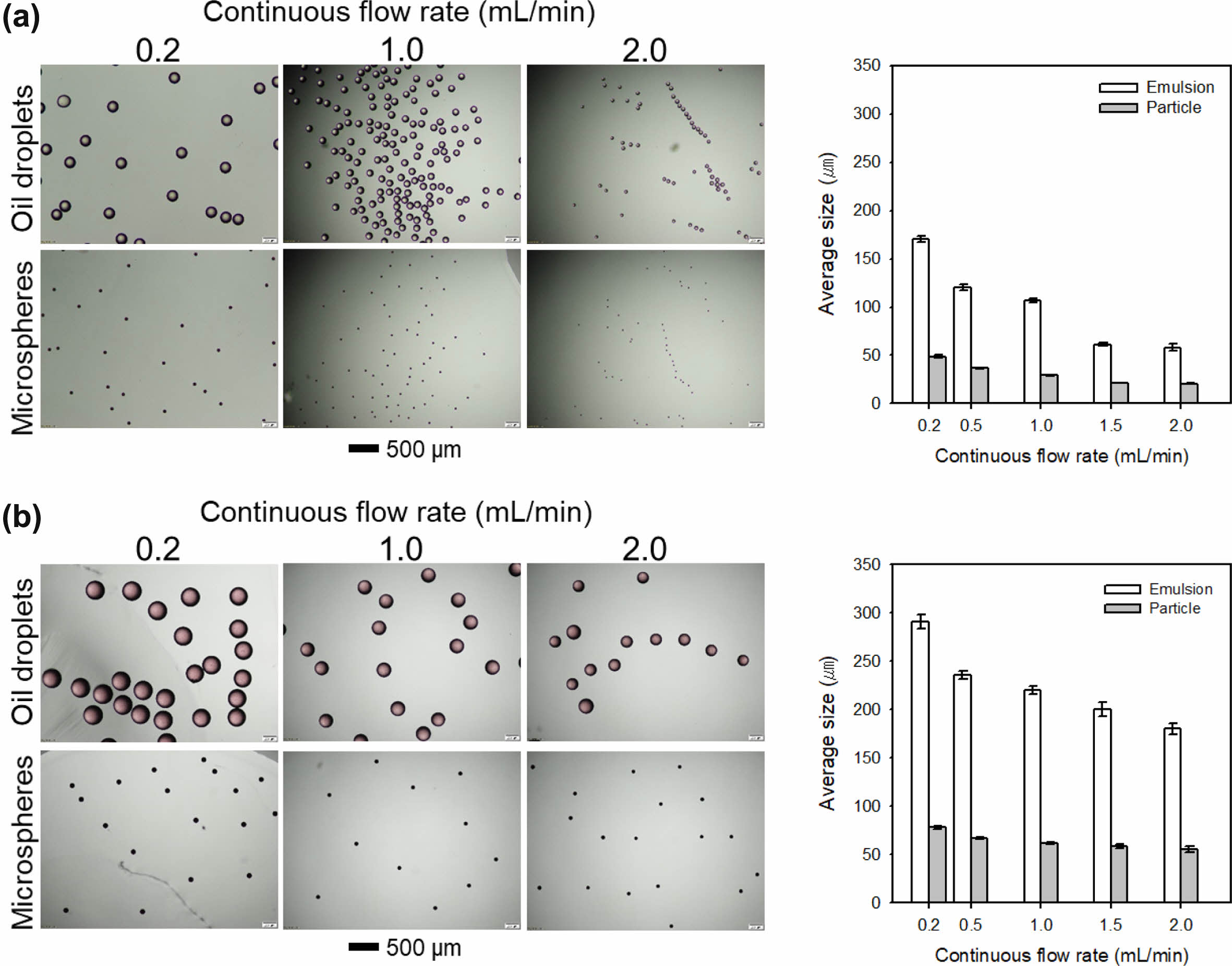
To evaluate the effect of the difference in the inner diameter of the glass capillary, an organic solution of PLA in DCM and an aqueous solution of PVA were introduced into the microfluidic device as the discontinuous and continuous phases, respectively. Figure 1(a) and 1(b) show the optical images of the generated oil droplets and PLA microspheres after solvent evaporation with respect to flow rate of the continuous phase and the inner diameter of the glass capillary. All the resultant oil droplets and microspheres exhibited uniform size distribution. At the small diameter of the glass capillary, the sizes of both oil droplets and microspheres were decreased with the increase in the flow rate of the continuous phase. The PLA microspheres of a size of 20.51±0.34 μm were produced at the flow rate of 2.0 mL/min of the continuous phase, which are suitable for sustained drug delivery carriers. Notably, the coefficient of variation (CV) values of the oil droplets at the use of the glass capillary with inner diameter of 300 μm ranged from 1.96 to 5.70%, which were larger than those of the samples (from 1.81 to 3.69%) prepared using the glass capillary with inner diameter of 200 μm. The difference in CV value was due to the silica microcapillary not being coaxially aligned to the glass capillary, as schematically shown in Figure 1(c).
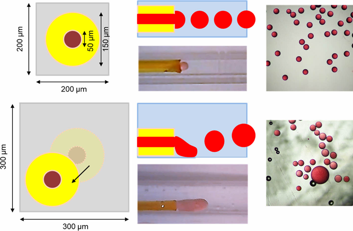
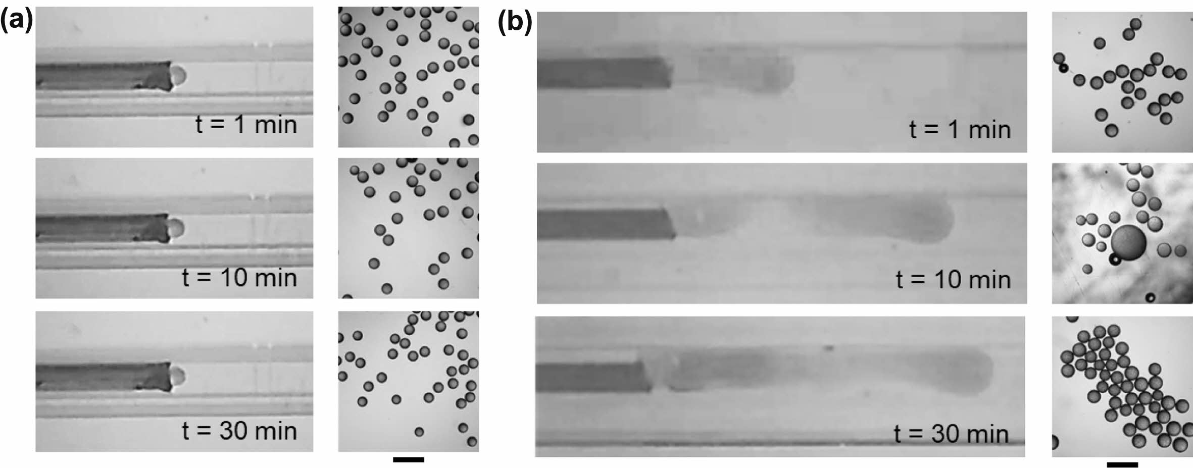
Figure 2 shows that uniform droplets were produced even with the use of the glass capillary with inner diameter of 300 μm. However, an inevitable issue for commercial applications is that non-uniform emulsions sometimes form, implying the problem of reproducibility. High reproducibility is considered one of the unique advantages of the droplet generation using a microfluidic approach, as well as size uniformity.21,22 To evaluate the reproducibility, we fabricated ten microfluidic devices using the glass capillary with different inner diameters (total twenty devices), and observed droplet generation behavior at the tip of the silica microcapillary at an initial stage (for 30 min). Figure 3 shows the optical images of droplet formation at the tip of the silica microcapillary and their corresponding oil droplets at the use of the glass capillary with 200 and 300 μm of inner diameter. In most cases, the microfluidic device with a small glass capillary continuously produced uniform droplets at the tip of the silica capillary in dripping mode (Figure 3(a)). However, non-uniform oil droplets were produced twice out of ten trials. Even worse, five out of ten microfluidic devices with the larger glass capillary failed to generate uniform oil droplets. As shown in Figure 3(b), the oil phase often flew along the inner wall of the large glass capillary and the oil droplets were generated at the end of the extended oil stream in jetting mode, resulting in non-uniform droplets.
Generally, a microfluidic approach demonstrates the continuous production of uniform droplets in a reliable and reproducible manner for a long period.23,24 However, undesirable jetting and clogging were often observed due to non-coaxial alignment and small precipitated polymer debris prepared during droplet formation.25,26 The unstable jetting mode and channel clogging issues should be addressed for practical applications, such as sustained drug carriers.27 In addition, water-miscible cosolvents (e.g., ethanol, methanol, and acetone) were often incorporated into the discontinuous DCM phase to enhance drug solubility.28,29 Therefore, the droplet generation behavior was observed using a mixture of DCM and acetone as the discontinuous phase. The DCM phase without acetone was generated into uniform droplets in a typical dripping mode. In contrast, when the DCM/acetone (8:2) phase was introduced into the microfluidic device with 200 μm glass capillary, non-uniform droplets were produced in jetting mode even at the early stage, which is due to the water miscibility of acetone. Therefore, a mixture of DCM and acetone (8:2) was used as the discontinuous phase in a model system.
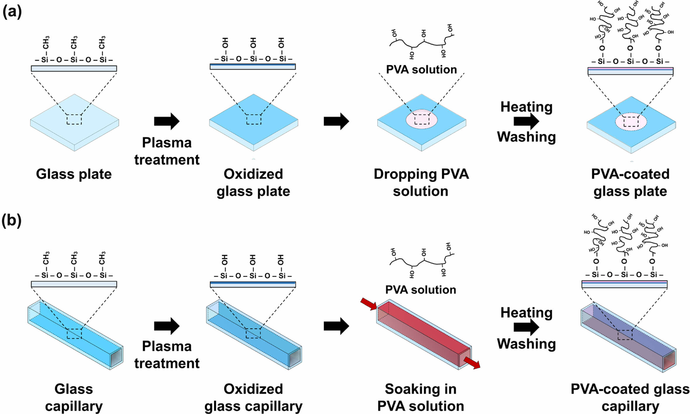
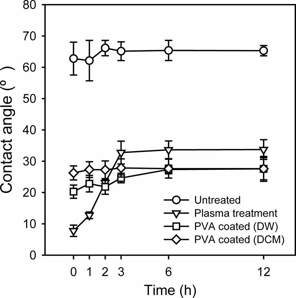
Actually, the flow of discontinuous phase along the inner wall of the outer capillary often originates from the attractive interaction between the discontinuous phase and the inner wall of the capillary.30,31 Therefore, surface modification was utilized to address this issue. PVA was chosen as a molecule for the surface modification because it is one of the most often used materials as a surfactant for the continuous phase in the oil-in-water emulsion. In addition, PVA can provide a thicker hydrophilic layer than silanes due to its larger molecular weight. Figure 4 shows a schematic diagram of the procedure of the modification of a glass substrate. A slide glass was treated with plasma and aqueous PVA solution was then dropped onto the plasma-treated glass surface, followed by baking in an oven.32 After washing with hot water, the contact angle was measured to ensure the PVA modification. The treated slide glass was soaked in water or DCM, and the water contact angle was then measured for 12 h. As shown in Figure 5, the untreated slide glass had a contact angle of approximately 65°, irrespective of time. The contact angle of the slide glass just after plasma treatment was 7.7°, but sharply increased to 32.7°. The slide glass treated by plasma and PVA modification showed a low contact angle of less than 30° over 12 h. A similar tendency was also observed in DCM soaking. This result confirmed the stable PVA modification onto the glass substrate for a long period in both aqueous and organic phases.
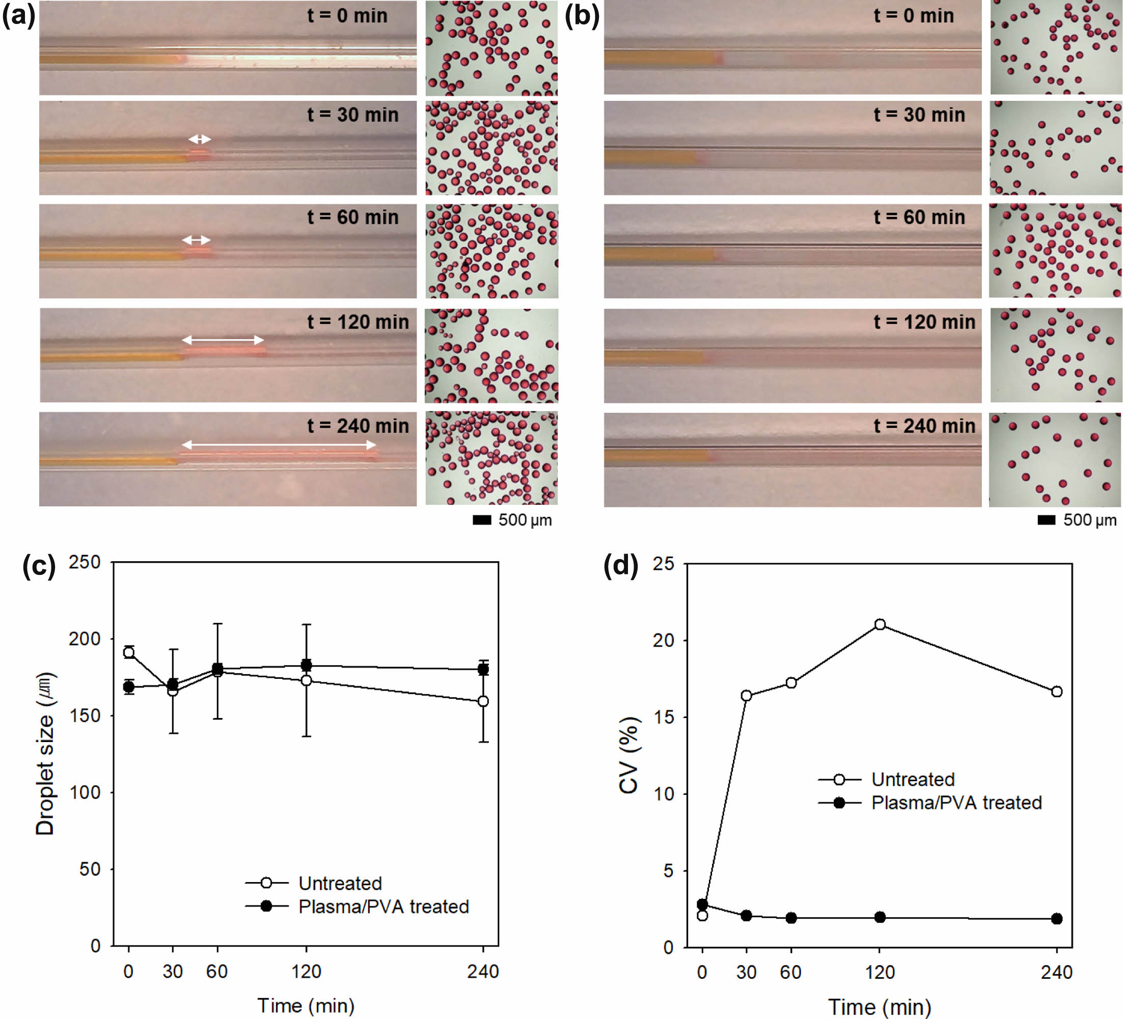
Generally, non-uniform oil droplets are generated in a hydrophobic microfluidic device because the oil phase tends to flow along the hydrophobic inner walls due to the hydrophobic interaction between the oil and the inner wall. The oil droplets are generated from the surface of the inner wall, not at the end of the microchannels for the oil phase. Therefore, the inner wall of the microfluidic device should be modified by hydrophilic molecules to prevent the hydrophobic interaction. To verify the effect of PVA modification, droplet generation behavior in the microfluidic device with 200 μm glass capillary was observed up to 6 h using a mixture of DCM and acetone as the discontinuous phase. The square glass capillary was treated in the plasma chamber and then soaked in aqueous PVA solution, followed by baking in oven. After washing with hot water several time, the PVA-coated glass capillary was used for the fabrication of the microfluidic device. Figure 6(a) shows that the stream of the oil phase (mixture of DCM and acetone) was elongated along the glass capillary with respect to time and DCM/acetone droplets were unstably produced in a jetting mode at the untreated microfluidic device. In contrast, the microfluidic device with the PVA-coated glass capillary exhibited stable droplet generation in dripping mode (Figure 6(b)). Figure 6(c) and 6(d) show the average size of the oil droplets and CVs, respectively. There was no significant difference in droplet size. The CV value of the oil droplets in the microfluidic device without PVA modification was increased up to 21.0%. However, the oil droplets produced in the microfluidic device modified with PVA exhibited high uniformity with CV less than 3%. This result suggests that the PVA modification the inner wall of the glass capillary was maintained for a relatively long time (up to 6 h), resulting in uniform droplet formation.
|
Figure 1 (a) A schematic of the microfluidic device consisting of the silica microcapillary and square glass capillary. Cross-sectional view of the microchannels in the microfluidic device consisting of square glass capillary with inner diameter of (b) 200 µm; (c) 300 µm. |
|
Figure 2 Representative optical images and average sizes of the resultant oil droplets and PLA microspheres prepared using the microfluidic device consisting of square glass capillary with inner diameter of (a) 200 µm; (b) 300 µm. |
|
Figure 3 Droplet formation at the tip of the silica capillary in the microfluidic device consisting of square glass capillary with inner diameter of (a) 200 µm; (b) 300 µm, with respect to time. Scale bars are 500 µm. |
|
Figure 4 Schematic of the PVA surface modification procedure of the (a) glass substrate; (b) glass capillary. |
|
Figure 5 Variation in water contact angle of the untreated, plasma treated, and plasma/PVA treated glass substrates with respect to time. The plasma/PVA treated glass substrates were soaked in distilled water (DW) or DCM phase |
|
Figure 6 (a, b) Droplet formation at the tip of the silica capillary in the microfluidic device consisting of square glass capillary with inner diameter of (a) 200 µm; (b) 300 µm, with respect to time. White arrows refer to the jetting length; (c) The average size; (d) CV values of oil droplets prepared in the microfluidic devices with untreated and plasma/PVA treated glass capillaries. |
The reproducible production of uniform droplets is a most important issue, which should be achieved for commercial applications. Here, we successfully demonstrated the stable and reproducible production of uniform oil droplets using a microfluidic device with a silica microcapillary and a square glass capillary (200 µm in diameter) modified with PVA. The small gap between the silica microcapillary and the square glass capillary facilitated the coaxial configuration of the capillaries. In addition, the PVA modification of the inner wall of the glass capillary prevented the discontinuous phase from flowing along the inner wall of the glass capillary. The capillary-based microfluidic device can provide a potential strategy for the mass production of uniform microspheres in a reliable and reproducible manner.
- 1. Chen, J.; Chen, D.; Xie, Y.; Yuan, T.; Chen, X. Progress of Microfluidics for Biology and Medicine. Nanomicro Lett. 2013, 5, 66-80.
- 2. Mashaghi, S.; Abbaspourrad, A.; Weitz, D. A.; van Oijen, A. M. Droplet Microfluidics: A Tool for Biology, Chemistry and Nanotechnology. Trends Analyt. Chem. 2016, 82, 118-125.
-

- 3. Tabeling, P. Recent Progress in the Physics of Microfluidics and Related Biotechnological Applications. Curr. Opin. Biotechnol. 2014, 25, 129-134.
-
- 4. Guo, J.; Yu, Y.; Cai, L.; Wang, Y.; Shi, K.; Shang, L.; Pan, J.; Zhao, Y. Microfluidics for Flexible Electronics. Mater. Today 2021, 44, 105-135.
-
- 5. Wang, J.; Shao, C.; Wang, Y.; Sun, L.; Zhao, Y. Microfluidics for Medical Additive Manufacturing. Engineering 2020, 6, 1244-1257.
-
- 6. Sia, S. K.; Whitesides, G. M. Microfluidic Devices Fabricated in Poly(dimethylsiloxane) for Biological Studies. Electrophoresis 2003, 24, 3563-3576.
-
- 7. Faustino, V.; Catarino, S. O.; Lima, R.; Minas, G. Biomedical Microfluidic Devices by Using Low-cost Fabrication Techniques: A Review. J. Biomech. 2016, 49, 2280-2292.
-
- 8. Raj M, K.; Chakraborty, S. PDMS Microfluidics: A Mini Review. J. Appl. Polym. Sci. 2020, 137, 48958.
-
- 9. Hwang, J.; Cho, Y. H.; Park, M. S.; Kim, B. H. Microchannel Fabrication on Glass Materials for Microfluidic Devices. Int. J. Precis. Eng. Manuf. 2019, 20, 479-495.
-
- 10. Poenar, D. P.; Iliescu, C.; Carp, M.; Pang, A. J.; Leck, K. J. Glass-based Microfluidic Device Fabricated by Parylene Wafer-to-wafer Bonding for Impedance Spectroscopy. Sens. Actuator A Phys. 2007, 139, 162-171.
-
- 11. Tsao, C.-W. Polymer Microfluidics: Simple, Low-Cost Fabrication Process Bridging Academic Lab Research to Commercialized Production. Micromachines 2016,7, 225.
-
- 12. Trantidou, T.; Elani, Y.; Parsons, E.; Ces, O. Hydrophilic Surface Modification of PDMS for Droplet Microfluidics Using a Simple, Quick, and Robust Method via PVA Deposition. Microsyst. Nanoeng. 2017, 3, 16091.
-
- 13. Mastiani, M.; Seo, S.; Riou, B.; Kim, M. High Inertial Microfluidics for Droplet Generation in a Flow-focusing Geometry. Biomed. Microdevices 2019, 21, 50.
-
- 14. Fu, T.; Wu, Y.; Ma, Y.; Li, H. Z. Droplet Formation and Breakup Dynamics in Microfluidic Flow-focusing Devices: From Dripping to Jetting. Chem. Eng. Sci. 2012, 84, 207-217.
-
- 15. Shakeri, A.; Khan, S.; Didar, T. F. Conventional and Emerging Strategies for the Fabrication and Functionalization of PDMS-Based Microfluidic Devices. Lab Chip 2021, 21, 3053-3075.
-
- 16. Jang, M.; Park, C. K.; Lee, N. Y. Modification of Polycarbonate with Hydrophilic/hydrophobic Coatings for the Fabrication of Microdevices. Sens. Actuators B Chem. 2014, 193, 599-607.
-
- 17. Lee, H.-C.; Wang, C.-Y.; Lin, C.-H. High-performance Humidity Sensors Utilizing Dopamine Biomolecule-coated Gold Nanoparticles. Sens. Actuators B Chem. 2014, 191, 204-210.
-
- 18. Sarvi, F.; Yue, Z.; Hourigan, K.; Thompson, M. C.; Chan, P. P. Y. Surface-functionalization of PDMS for Potential Micro-bioreactor and Embryonic Stem Cell Culture Applications. J. Mater. Chem. B 2013, 1, 987-996.
-
- 19. Long, H. P.; Lai, C. C.; Chung, C. K. Polyethylene Glycol Coating for Hydrophilicity Enhancement of Polydimethylsiloxane Self-driven Microfluidic Chip. Surf. Coat. Technol. 2017, 320, 315-319.
-
- 20. Wu, D.; Luo, Y.; Zhou, X.; Dai, Z.; Lin, B. Multilayer Poly(vinyl alcohol)-adsorbed Coating on Poly(dimethylsiloxane) Microfluidic Chips for Biopolymer Separation. Electrophoresis 2005, 26, 211-218.
-
- 21. Wiedemeier, S.; Eichler, M.; Römer, R.; Grodrian, A.; Lemke, K.; Nagel, K.; Klages, C.-P.; Gastrock, G. Parametric Studies on Droplet Generation Reproducibility for Applications with Biological Relevant Fluids. Eng. Life Sci. 2017, 17, 1271-1280.
-
- 22. Imani Moqadam, S.; Baune, M.; Bösing, I.; Heinzel, C.; Meyer, D.; Thomann, A.; Wielki, N.; Ellendt, N. Reproducibility of High-Throughput Sample Properties Produced by a High-Temperature Molten Metal Droplet Generator. Metals 2020,10, 297.
-
- 23. Martins, J. P.; Torrieri, G.; Santos, H. A. The Importance of Microfluidics for the Preparation of Nanoparticles as Advanced Drug Delivery Systems. Expert Opin. Drug Deliv. 2018, 15, 469-479.
-
- 24. Rezvantalab, S.; Keshavarz Moraveji, M. Microfluidic Assisted Synthesis of PLGA Drug Delivery Systems. RSC Adv. 2019, 9, 2055-2072.
-
- 25. Zhang, J.; Wang, C.; Liu, X.; Yi, C.; Wang, Z. L. Experimental Studies of Microchannel Tapering on Droplet Forming Acceleration in Liquid Paraffin/Ethanol Coaxial Flows. Materials 2020, 13, 944.
-
- 26. Dressaire, E.; Sauret, A. Clogging of Microfluidic Systems. Soft Matter 2017, 13, 37-48.
-
- 27. Park, Y.; Pham, T. A.; Beigie, C.; Cabodi, M.; Cleveland, R. O.; Nagy, J. O.; Wong, J. Y. Monodisperse Micro-Oil Droplets Stabilized by Polymerizable Phospholipid Coatings as Potential Drug Carriers. Langmuir 2015, 31, 9762-9770.
-
- 28. Kearney, M.-C.; McKenna, P. E.; Quinn, H. L.; Courtenay, A. J.; Larrañeta, E.; Donnelly, R. F. Design and Development of Liquid Drug Reservoirs for Microneedle Delivery of Poorly Soluble Drug Molecules. Pharmaceutics 2019, 11, 605.
-
- 29. Agrawal, A. G.; Kumar, A.; Gide, P. S. Formulation of Solid Self-nanoemulsifying Drug Delivery Systems Using N-methyl Pyrrolidone as Cosolvent. Drug Dev. Ind. Pharm. 2015, 41, 594-604.
-
- 30. Wang, S.; Yang, X.; Wu, F.; Min, L.; Chen, X.; Hou, X. Inner Surface Design of Functional Microchannels for Microscale Flow Control. Small 2020, 16, 1905318.
-
- 31. Doufène, K.; Tourné-Péteilh, C.; Etienne, P.; Aubert-Pouëssel, A. Microfluidic Systems for Droplet Generation in Aqueous Continuous Phases: A Focus Review. Langmuir 2019, 35, 12597-12612.
-
- 32. Al Nahas, K.; Cama, J.; Schaich, M.; Hammond, K.; Deshpande, S.; Dekker, C.; Ryadnov, M. G.; Keyser, U. F. A Microfluidic Platform for the Characterisation of Membrane Active Antimicrobials. Lab Chip 2019, 19, 837-844.
-
- Polymer(Korea) 폴리머
- Frequency : Bimonthly(odd)
ISSN 0379-153X(Print)
ISSN 2234-8077(Online)
Abbr. Polym. Korea - 2024 Impact Factor : 0.6
- Indexed in SCIE
 This Article
-
2023; 47(5): 582-589
Published online Sep 25, 2023
- 10.7317/pk.2023.47.5.582
- Received on Mar 7, 2023
- Revised on May 29, 2023
- Accepted on Jul 28, 2023
Services
- Full Text PDF
- Abstract
- ToC
- Acknowledgements
- Conflict of Interest
Introduction
Experimental
Results and Discussion
Conclusions
- References
Shared
Correspondence to
- Min-Ho Kang. Sung-Wook Choi
-
*Biomedical and Chemical Engineering, The Catholic University of Korea, 43 Jibong-ro, Wonmi-gu, Bucheon-si, Gyeonggi-do 14662, Korea
**Department of Biotechnology, The Catholic University of Korea, 43 Jibong-ro, Wonmi-gu, Bucheon-si, Gyeonggi-do 14662, Korea - E-mail: mhkang@catholic.ac.kr, choisw@catholic.ac.kr
- ORCID:
0000-0002-1342-0077, 0000-0002-5075-8798
Hyecheon Building(Room 601), #354, Gangnam-Daero, Gangnam-Gu, Seoul 06242, Korea
TEL : 82-2-568-3860, 561-5203, 569-3860 FAX : 82-2553-6938 E-mail: polymer@polymer.or.kr