


- Aligned Non-Oxidized Graphene Flake/PDMS Composites with Enhanced Mechanical Properties
Ja Yoon Lee, In-Hyeok Hwang, Saeed Habibpour*, and Yun-Seok Jun†

Department of Polymer Engineering, Pukyong National University, 45 Yongso-ro, Nam-gu, Busan 48513, Korea
*Department of Chemical Engineering, University of Waterloo, 200 University Avenue West, Waterloo, Ontario, Canada N2L 3G1- 기계적 물성이 향상된 배향 비산화 그래핀/PDMS 복합재
이자윤 · 황인혁 · Saeed Habibpour* · 전윤석†
국립 부경대학교 고분자공학전공, *워털루 대학교 화학공학과
Reproduction, stored in a retrieval system, or transmitted in any form of any part of this publication is permitted only by written permission from the Polymer Society of Korea.
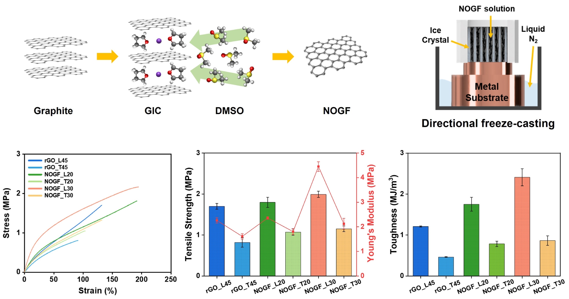
In this study, we report the fabrication of high-performance polymer nanocomposites by incorporating directionally aligned non-oxidized graphene flakes (NOGF) into a polydimethylsiloxane (PDMS) matrix. NOGF was synthesized via exfoliation of graphite intercalation compounds (GIC) without oxidative treatment, preserving its graphitic structure and minimizing defect formation. A unidirectional freeze-casting method was employed to construct highly aligned three-dimensional NOGF aerogels, which were then infiltrated with PDMS to produce flexible, lightweight composites. The resulting NOGF/PDMS composites exhibited markedly improved mechanical properties compared to reduced graphene oxide (rGO)-based composites, achieving a tensile strength of 2.0 MPa, a Young’s modulus of 4.5 MPa, and a toughness of 2.4 MJ/m3, while rGO/PDMS composites reached 1.7 MPa, 2.3 MPa, and 1.2 MJ/m3, respectively. These improvements are attributed to the structural integrity and low defect density of NOGF. This work demonstrates that employing defect-suppressed, aligned graphene architectures offers an effective strategy for reinforcing polymer matrices, even at low filler content, providing a promising platform for developing mechanically robust nanocomposites.
본 연구에서는 방향성 있게 정렬된 비산화 그래핀 플레이크(non-oxidized graphene flakes, NOGFs)를 PDMS와 복합화하여 고성능 고분자 나노 복합재를 제작하였다. 흑연 삽입화합물(GIC)을 산화 처리 없이 박리하여 합성한 NOGF는 구조적 완전성과 낮은 결함 밀도를 유지하였으며, 단일 방향 동결주조법을 통해 3차원 에어로겔을 형성하였다. 결과적으로 얻어진 NOGF/PDMS 복합체는 환원 그래핀 산화물(rGO)을 기반으로 한 복합재에 비해 현저히 향상된 기계적 물성을 나타내었다. 인장 강도는 2.0 MPa, 영률은 4.5 MPa, 인성은 2.4 MJ/m3로, rGO/PDMS 복합체의 1.7 MPa, 2.3 MPa, 1.2 MJ/m3에 비해 우수한 물성을 보였다. 이러한 향상은 NOGF의 구조적 완전성과 낮은 결함 밀도에 기인한다. 본 연구는 결함이 억제된 정렬 그래핀 구조체를 활용하여, 낮은 충전제 함량에서도 기계적 물성이 우수한 나노복합체 개발 전략을 제시한다.
Non-oxidized graphene flakes (NOGF) with minimal defects were synthesized and directionally aligned using unidirectional freeze casting. The resulting NOGF/PDMS composites exhibited significantly improved mechanical properties compared to rGO-based counterparts, particularly in the longitudinal direction.
Keywords: non-oxidized graphene flakes, reduced graphene oxide, unidirectional freeze-casting, anisotropic structure, mechanical properties.
This work was supported by Korea Evaluation Institute of Industrial Technology (KEIT) grant funded by the Korea government (MOTIE) (No. RS-2024-00421052). This work is also supported by the Global Joint Research Program funded by the Pukyong National University (202506020001).
The authors declare that there is no conflict of interest.
The growing demand for lightweight, flexible, and mechanically robust materials in next-generation electronic devices, such as wearable sensors, stretchable circuits, and soft robotics, has driven extensive research into polymer-based nanocomposites reinforced with two-dimensional (2D) carbon materials.1-3 In this context, nanoporous 2D filler–based composites, including graphene aerogels and foams embedded in polymer matrices, have attracted increasing attention due to their three-dimensional (3D) cellular architectures, which combine low density with enhanced stiffness and strength.
Most previous studies have focused on nanocomposites in which 2D or 1D carbon fillers, such as reduced graphene oxide (rGO), graphene nanoplatelets, and carbon nanotubes are randomly dispersed within a polymer matrix.4-11 Although these fillers possess high aspect ratios and intrinsic stiffness, their reinforcement efficiency is often limited by structural defects, residual functional groups, and weak interfacial bonding, which hinder effective stress transfer.12-14 Polymer-infiltrated 3D graphene frameworks have also been explored as load-bearing skeletons; however, research to date has primarily emphasized compressive behavior, and systematic investigations of tensile properties and mechanical anisotropy remain scarce. In particular, there is little direct comparison of composites containing graphene networks derived from different synthesis routes (e.g. chemically oxidized rGO versus non-oxidatively exfoliated graphene) under the same polymer matrix and processing conditions.
To overcome these issues, non-oxidized graphene flakes (NOGF), produced via liquid-phase exfoliation of graphite intercalation compounds (GICs), were employed as an alternative to rGO. Unlike rGO, which undergoes aggressive chemical oxidation and thermal reduction steps, NOGF preserves the intrinsic sp²-hybridized carbon lattice with minimal disruption. This structural integrity imparts higher intrinsic strength and stiffness, as well as improved compatibility with the polymer matrix, making NOGF a superior candidate for mechanical reinforcement.
In this study, both NOGF and rGO foams were prepared using a unidirectional freeze-casting technique, which produces anisotropically aligned porous structures. These foams were then infiltrated with a polydimethylsiloxane (PDMS) precursor to fabricate composite specimens with highly ordered filler alignment. PDMS was selected as a matrix due to its low stiffness; when the matrix has a low Young’s modulus, the reinforcing effect of the filler can be readily observed. Additionally, the composite was produced via aerogel infiltration, which allows for reduced filler loading. Because the NOGF and rGO produced in this study are microscale, a typical compounding system is not favorable, as it usually requires a large amount of fillers. The resulting NOGF/PDMS composites exhibited substantially improved mechanical performance, including higher tensile strength (2.0 MPa), Young’s modulus (4.5 MPa), and toughness (2.4 MJ/m3) compared to rGO/PDMS counterparts (tensile strength: 1.7 MPa, Young’s modulus: 2.3 MPa, toughness: 1.2 MJ/m3). This enhancement is attributed to the superior structural quality of NOGF and the formation of an aligned, percolated filler network that enables efficient load transfer along the longitudinal direction. These findings underscore the importance of both filler quality and microstructural anisotropy in achieving mechanically robust nanocomposites. The use of defect-minimized graphene and directional alignment offers a practical and scalable route to developing high-performance polymer composites for flexible and wearable mechanical systems.
Materials. Natural graphite flakes (≥80%, +50 mesh), polyvinylpyrrolidone (PVP), and poly(vinyl alcohol) (PVA, Mw = 31000–50000) were purchased from Sigma-Aldrich. Additional natural graphite powder (2–15 μm) and bulk potassium metal were obtained from Thermo Fisher Scientific. Naphthalene and hydrochloric acid were sourced from Samchun Pure Chemical Co. Anhydrous tetrahydrofuran (THF), phosphoric acid, and hydrogen peroxide were supplied by Daejung Chemicals Co. Cyclohexane, dimethyl sulfoxide (DMSO), sulfuric acid, and potassium permanganate were provided by Duksan Pure Chemical Co. The PDMS (Sylgard 184) used in this study was procured from Dow Corning Inc.
Preparation of Graphene Oxide and Non-oxidized Graphene Flake. Graphene oxide (GO) was synthesized from graphite (natural, 2–15 μm) via an improved Hummer’s method developed by James Tour.15 In this procedure, graphite flakes were dispersed in a mixed acid solution consisting of sulfuric acid and phosphoric acid in a 9:1 volume ratio. Potassium permanganate was then gradually introduced into the mixture, and the oxidation reaction was maintained at 50 ℃ for 16 hours. Upon completion of the reaction, deionized water and hydrogen peroxide were added to terminate the oxidation. The resulting suspension was thoroughly washed multiple times with deionized water, hydrochloric acid, and ethanol to remove residual reactants and byproducts, yielding purified GO.
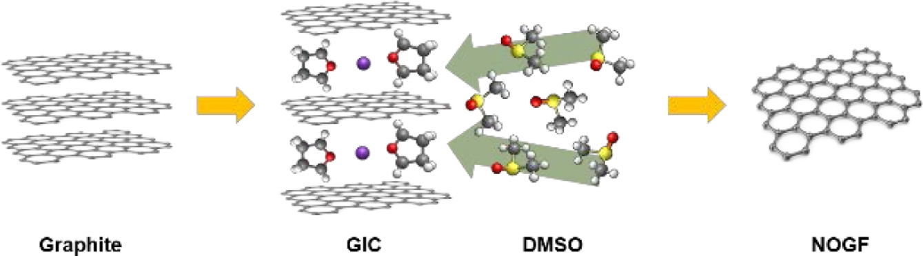
The synthesis procedure for is outlined in Figure 1. NOGF was derived from a ternary GICs (t-GICs), as described in previous literature.16 To begin, potassium metal and naphthalene were dissolved in anhydrous THF to generate a potassium-naphthalenide solution. Once full dissolution of potassium was achieved, natural graphite flakes (≥80%, +50 mesh) were introduced into the solution at a carbon-to-potassium ionic ratio of 5:1. The mixture was maintained under reaction conditions for 16 hours to ensure complete intercalation of the graphite. Following the intercalation process, the excess potassium-naphthalenide solution was removed, and the resulting t-GICs was briefly rinsed with excess cyclohexane to eliminate surface-bound naphthalene residues. The cleaned t-GICs was then dispersed in a PVP–DMSO solution, maintaining a 1:1 weight ratio between graphite and PVP. The dispersion underwent bath sonication for 45 minutes to facilitate exfoliation. After resting for two days to allow sedimentation of unexfoliated residues, the supernatant was collected and centrifuged at 10000 rpm for 45 minutes to isolate the few-layered NOGF.
Preparation of Reduced Graphene Oxide/PDMS, Non-oxidized Graphene Flakes/PDMS Composites. The GO solution was cast into a Teflon mold and subjected to unidirectional freeze-casting by placing the mold on a metal plate submerged in liquid nitrogen. After complete solidification, the frozen samples were freeze-dried for 96 hours to yield a porous GO foam structure. This foam was then thermally reduced in an argon atmosphere at 900 ℃ to obtain the rGO foam. In parallel, the PDMS precursor was prepared by mixing Sylgard 184 base and curing agent at a weight ratio of 10:1 and subsequently infiltrated into the rGO foam to fabricate the composite.
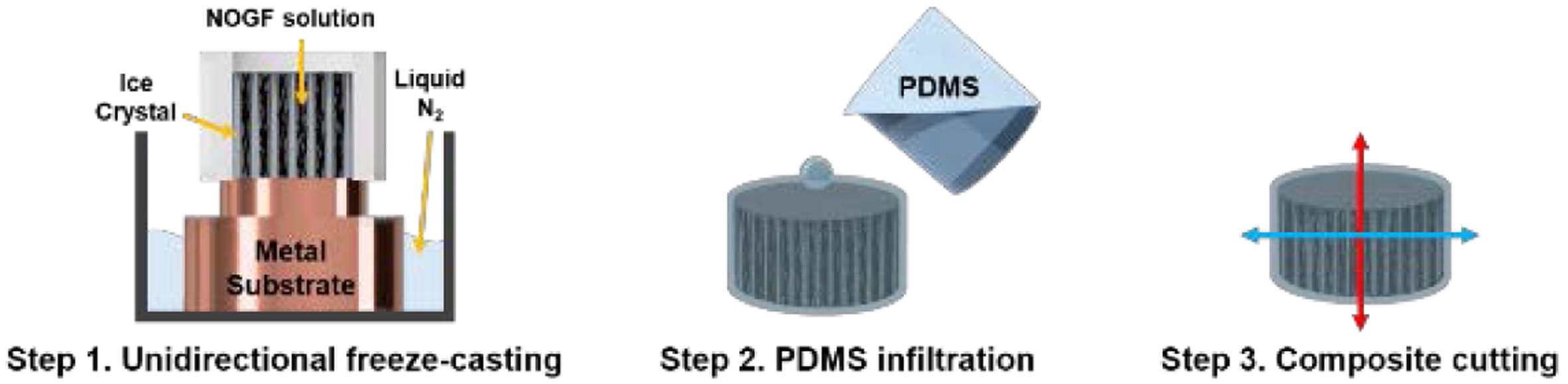
Using a procedure analogous to that employed for the GO foam, the NOGF foam was fabricated by dispersing few-layered NOGF in a PVA–deionized water solution, followed by freeze-drying and subsequent infiltration with PDMS. The overall fabrication process of the rGO/PDMS and NOGF/PDMS composites is illustrated in Figure 2.
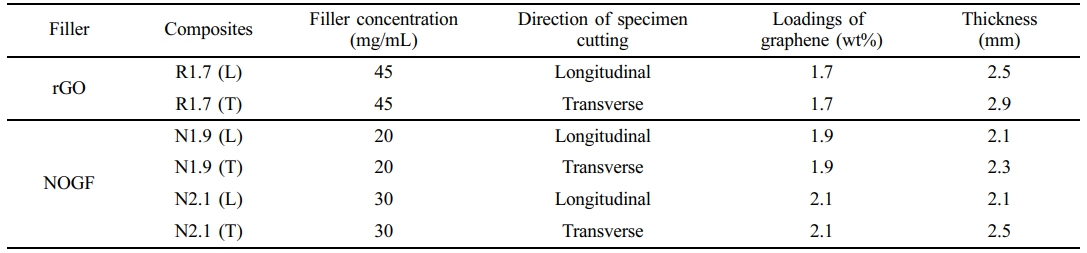
In the case of the rGO foam, thermal reduction is necessary to eliminate oxygenated groups, as described above. This leads to significant mass loss in the rGO foam after reduction. In contrast, the NOGF foam did not require a reduction step, as the flakes were already in a non-oxidized state. Therefore, to compensate for this loss of rGO foam and achieve a similar filler content, a higher initial concentration of rGO was required. Both types of composites were degassed in a desiccator for 5 minutes and thermally cured at 80 ℃ for 6 hours. The cured composites were then sectioned into rectangular specimens with two orientations: longitudinal (L), cut parallel to the direction of ice crystal growth, and transverse (T), cut perpendicular to it. All composite samples used in this study are summarized in Table 1.
Characterization. The morphology and lateral dimensions of individual rGO and NOGF sheets were examined using transmission electron microscopy (TEM, JEM-F200, JEOL). X-ray diffraction (XRD, Ultima IV, Rigaku) was performed to investigate the crystalline structures of graphite, rGO, and NOGF foams. Raman spectroscopy (NRS-5100, 532 nm, JASCO) was employed to evaluate the degree of structural defects and disorder in the foams. Scanning electron microscopy (SEM, MIRA3 LMH, TESCAN) was utilized to observe the microstructures of both the foams and their corresponding PDMS composites. Mechanical properties were assessed via stress-strain measurements using a universal testing machine (UTM, 36SC-1, Instron) equipped with a 1 kN load cell and operated at a crosshead speed of 5 mm/min under ambient conditions. Specimens were cut into rectangular dimensions of 22.7×10×2.0 mm³, and a minimum of five samples per composite type were tested to ensure reproducibility.
|
Figure 1 Illustration of the NOGF preparation method. |
|
Figure 2 Schematic illustration of fabrication process for the composites prepared in this study. |
Material Characterizations. The exfoliation of NOGF and rGO with few layers was confirmed by the TEM in Figure 3(a) and (b). A comparative analysis of the individual graphene sheets revealed no substantial disparities in size.
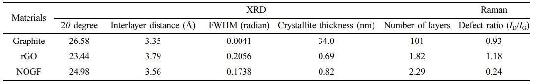
Figure 3(c) displays the XRD patterns of pristine graphite, rGO, and NOGF, highlighting the structural changes that occur during the exfoliation process. For both rGO and NOGF, the (002) diffraction peak shows a marked decrease in intensity and noticeable broadening, which suggests the breakdown of the graphitic layered structure as a result of exfoliation. The interlayer spacing (in Å) was determined using Bragg’s law, while the crystallite thickness along the c-axis (D) was calculated using the Debye–Scherrer equation (Eq. 1),
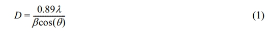
where λ represents the X-ray wavelength, and β denotes the full width at half maximum (FWHM) of the corresponding diffraction peak.17-19 For sp2-hybridized carbon materials, the D value is indicative of the average thickness of the graphitic stacking. Under the assumption of regular stacking with consistent interlayer spacing, the number of graphene layers can be estimated by dividing the D value by the interlayer distance (Eq. 2).
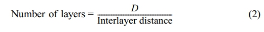
Table 2 presents the interlayer structural parameters of graphite, rGO, and NOGF, which were calculated based on Bragg’s law.
To investigate the structural characteristics of the carbon-based materials in more detail, Raman spectroscopy was utilized to evaluate their level of disorder and defect concentration,20,21 as shown in Figure 3(d). The analysis focused on the G-band, which corresponds to the in-plane stretching of sp² carbon–carbon bonds, and the D-band, which is typically associated with lattice imperfections and structural disorder. The intensity ratio of the D-band to G-band (ID/IG) was used as an indicator of defect density. The measured (ID/IG) values were 0.93 for pristine graphite, 1.14 for rGO, and notably lower at 0.19 for NOGF. This low ratio for NOGF suggests that the material retained a highly ordered structure with minimal oxidative damage to the basal plane. A summary of the Raman spectral parameters is provided in Table 2.
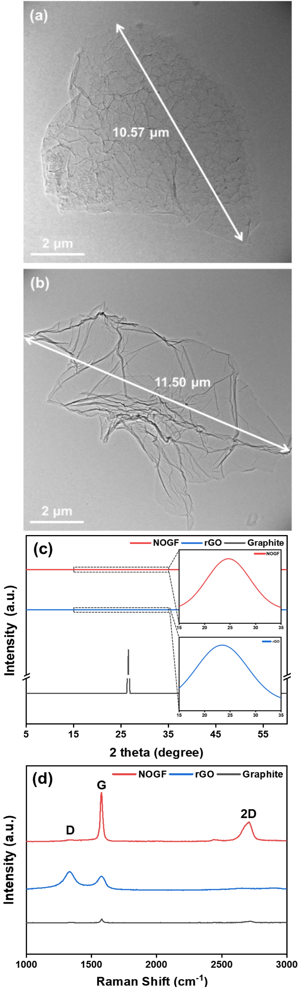
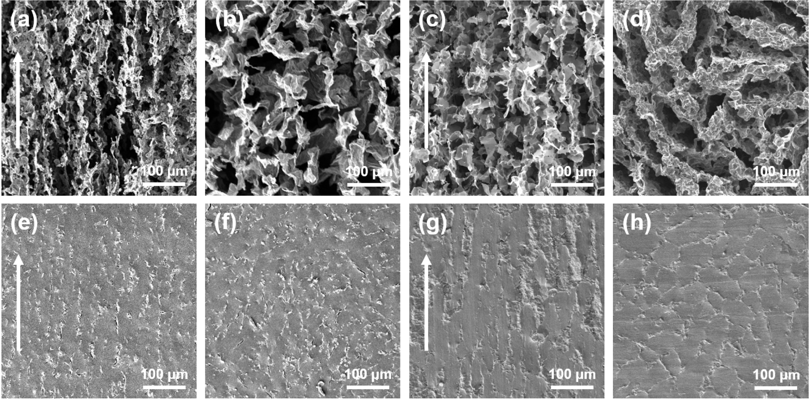
Morphology of NOGF Foam and NOGF/PDMS Composites. The microstructures of the rGO and NOGF foams, as well as their corresponding composites, were examined via SEM, with attention given to both longitudinal and transverse cross-sections. As shown in Figure 4(a) and (c), the longitudinal sections of the rGO and NOGF foams display distinct structural alignment, while the transverse sections are presented in Figure 4(b) and (d) respectively.
The freeze-casting technique produced a directionally aligned porous architecture along the freeze direction, characterized by elongated pores and interconnected graphene walls. SEM images also reveal that the graphene layers are uniformly distributed within the pore channels, confirming that the unidirectional freeze-casting method effectively induces anisotropic structuring.
Figure 4(e) and (f), as well as 4(g) and (h), show the internal morphology of the rGO/PDMS and NOGF/PDMS composites in the longitudinal and transverse orientations, respectively. In the longitudinal views, the PDMS matrix appears relatively dense and smooth, with only minor disturbances caused by the embedded graphene framework. Likewise, the transverse images reveal a uniform dispersion of graphene within the matrix, indicating that the foam was effectively impregnated during the composite fabrication process. These findings collectively confirm that the anisotropic structure imparted by the freeze-casting process is preserved after PDMS infiltration and composite formation.
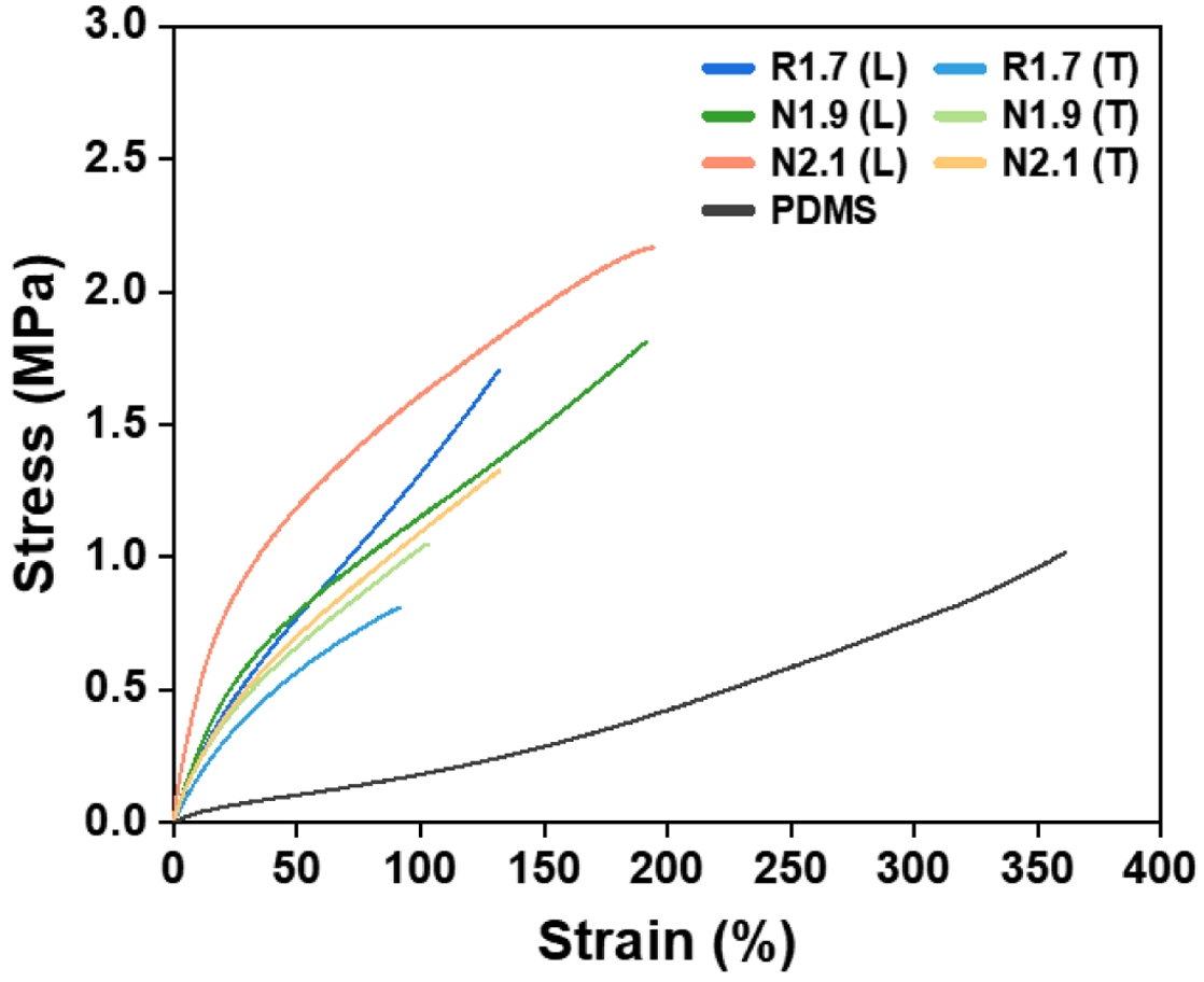
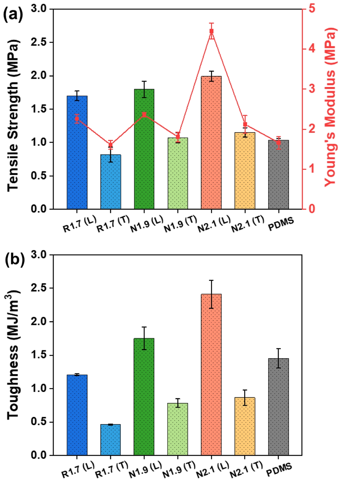
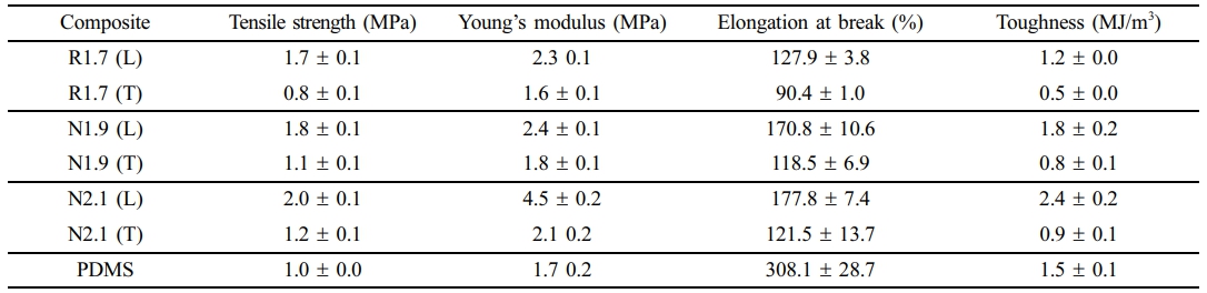
Mechanical Strength. Figure 5 shows the stress-strain curves of the rGO and NOGF composites and neat PDMS, and Figure 6 summarizes the corresponding tensile strength, Young’s modulus, and toughness. Neat PDMS exhibits a tensile strength of 1.0 MPa, a Young’s modulus of 1.7 MPa, an elongation at break of about 308 %, and a toughness of 1.5 MJ/m3, thereby demonstrating a soft and highly ductile property. Upon introducing the graphene frameworks, all composites show clear reinforcement relative to neat PDMS. In particular, N2.1 (L) nearly doubles the tensile strength (2.0 MPa and 1.0 MPa, respectively) and provides more than twice the Young’s modulus (4.5 MPa and 1.7 MPa, respectively), while its toughness increases from 1.5 to 2.4 MJ/m3. Among the composites, the NOGF/PDMS series consistently exhibits higher strength, stiffness, and toughness than the rGO/PDMS, as summarized in Table 3. For example, N2.1 (L) exhibited a tensile strength of 2.0 MPa, a Young’s modulus of 4.5 MPa and a toughness of 2.4 MJ/m3, which are markedly higher than those of R1.7 (L) (1.7 MPa, 2.3 MPa, and 1.2 MJ/m3, respectively). These enhancements are attributed to the intrinsic structural integrity of NOGF, which maintains a continuous sp2-conjugated carbon lattice with minimal defects.16,22 This structure exhibits fewer defects, vacancies, and residual oxygen functional groups, resulting in enhanced intrinsic strength and stiffness within individual flakes.22 Furthermore, this configuration facilitates gradual energy dissipation during deformation, thereby contributing to increased toughness. In contrast, rGO is susceptible to structural degradation due to chemical oxidation and thermal reduction processes, which inherently introduce irreversible lattice defects and disrupt the extended π-conjugation network.23,24 Consequently, load-bearing continuity is compromised, and the filler’s capacity to accommodate strain energy is diminished, leading to reduced stiffness, lower strength, and brittle failure behavior.25,26 From an interfacial perspective, the NOGF surface consists of relatively uniform sp² carbon planes, facilitating van der Waals interactions and mechanical interlocking with the non-polar PDMS chains.27 During the PDMS infiltration process after freeze-casting, the matrix uniformly wets the pore interiors and skeleton surfaces, forming a relatively homogeneous load-transfer network across the entire interface. This phenomenon enables gradual deformation and dissipation of energy at the interface between filler and the matrix under tensile stress, delaying crack initiation and propagation. Consequently, both strength and Young’s modulus, as well as toughness, are simultaneously enhanced. Conversely, rGO manifests oxygen-containing functional groups distributed irregularly, leading to the formation of locally brittle domains. This is potentially reducing interfacial wettability and cohesion. At such heterogeneous interfaces, stress concentration readily occurs during deformation, and load transfer becomes inefficient due to interface debonding or micro-pore formation.25 Consequently, rGO/PDMS composites exhibit relatively low tensile strength and stiffness, along with more brittle fracture behavior. In summary, NOGF provides significantly more efficient reinforcement than rGO at the same filler content because it forms a more intact skeletal structure and a more homogeneous and robust interfacial network.
Although the NOGF/PDMS composites were prepared with slightly higher graphene contents than the rGO/PDMS composites, the difference in filler loading may only make a minor contribution to the overall mechanical response and thus cannot be entirely excluded. However, the magnitude and consistency of the improvements observed in tensile strength, modulus, and toughness indicate that the dominant factor is the superior quality of the NOGF network, which enables more efficient interfacial load transfer within the PDMS matrix.
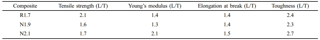
In addition, due to the anisotropic microstructure induced by the unidirectional freeze-casting process, the graphene/PDMS composites exhibit direction-dependent mechanical behavior. Specimens tested along the alignment direction (longitudinal) display significantly higher tensile strength, Young’s modulus, and toughness than those tested perpendicular to the alignment direction (transverse). To quantify the mechanical anisotropy induced by unidirectional freeze-casting, the ratios of longitudinal to transverse tensile properties (L/T) were calculated for each composite (Table 4). For all samples, the tensile strength in the longitudinal direction is approximately 1.6 to 2.1 times higher than that in the transverse direction, and the Young’s modulus shows a similar enhancement, with L/T ratios ranging from 1.3 to 2.1. The elongation at break is also greater along the alignment direction, with L/T ratios of 1.4 to 1.5, indicating that the aligned structure not only stiffens the material but also preserves its ductility. Most notably, the toughness in the longitudinal direction is 2.3 to 2.7 times greater than in the transverse direction, confirming that freeze-casting facilitates more efficient energy dissipation when loaded parallel to the graphene alignment. This disparity can be attributed to the anisotropic arrangement of graphene sheets within the framework. When a tensile load is applied parallel to the alignment direction, stress is primarily carried along the continuous graphene pathways, enabling efficient stress transfer and distribution. Furthermore, localized interfacial mobility between the graphene and the PDMS matrix facilitates strain accommodation and mechanical dissipation. These deformation mechanisms contribute to delayed crack propagation and enhanced tensile strength, modulus, elongation at break, and toughness in the longitudinally aligned samples.7,28-31 Conversely, under transverse loading, stress transfer occurs predominantly through the soft PDMS matrix and the discontinuous, transversely oriented graphene domains. In this orientation, the load-bearing capability of the graphene network is reduced, and the applied stress is less effectively distributed, leading to localized stress concentration and premature failure. As a result, mechanical performance in the transverse direction is significantly compromised.28,31 This effect is evident in the N2.1 (T) specimen, which exhibits lower tensile strength, modulus, and toughness compared to the N1.9 (L) specimen, despite having a higher graphene content. Consequently, the N2.1 (L) specimen, which possesses a higher filler content and an alignment direction parallel to the applied tensile load, demonstrates the most favorable mechanical performance among the tested samples.
|
Figure 3 TEM images of (a) NOGF; (b) rGO; (c) XRD; (d) Raman spectra of pristine graphite, rGO and NOGF, respectively. |
|
Figure 4 SEM images of rGO foams: (a) longitudinal; (b) transverse and PDMS composites; (e) longitudinal; (f) transverse NOGF fomas; (c) longitudinal; (d) transverse and PDMS composites; (g) longitudinal; (h) transverse. |
|
Figure 5 Tensile stress-strain curves of rGO, NOGF composites and PDMS. |
|
Figure 6 Mechanical properties of rGO, NOGF composites and PDMS: (a) tensile strength and Young’s modulus; (b) toughness. |
|
Table 3 Tensile Strength, Young’s Modulus, Elongation at Break, and Toughness of Composites |
|
Table 4 Longitudinal-to-transverse (L/T) Ratio of Tensile Properties for Graphene/PDMS Composites |
In this study, NOGFs were synthesized through the exfoliation of graphite intercalation compounds, effectively retaining the intrinsic structure of graphene with minimal introduction of defects. Structural analyses via TEM, XRD, and Raman spectroscopy confirmed the high crystallinity and low defect density of the resulting NOGF. By employing a unidirectional freeze-casting process, the NOGF was assembled into a highly aligned three-dimensional aerogel network, which was subsequently infiltrated with PDMS to form nanocomposites. The resulting NOGF/PDMS composites demonstrated significant improvements in mechanical performance, including a tensile strength of 2.0 MPa, Young’s modulus of 4.5 MPa, and toughness of 2.4 MJ/m3, compared to rGO/PDMS composites with tensile strength of 1.7 MPa, Young’s modulus of 2.3 MPa, and toughness of 1.2 MJ/m3. These enhancements are attributed to the structural integrity of the NOGF and the formation of a well-aligned and interconnected filler network that promotes efficient stress transfer and energy dissipation. The results highlight the potential of using high-quality graphene with controlled alignment to fabricate flexible and mechanically robust polymer nanocomposites at low filler loadings.
- 1. Kiran, M. D.; Govindaraju, H. K.; Jayaraju, T.; Kumar, N. Review-Effect of Fillers on Mechanical Properties of Polymer Matrix Composites. Mater. Today. Proc. 2018, 5, 22421-22424.
-

- 2. Pinto, G. M.; Cremonezzi, J. M. O.; Ribeiro, H.; Andrade, R. J. E.; Demarquette, N. R.; Fechine, G. J. M. From Two-Dimensional Materials to Polymer Nanocomposites with Emerging Multifunctional Applications: A Critical Review. Polym. Compos. 2023, 44, 1438-1470.
-
- 3. Qadir, A.; Le, T. K.; Malik, M.; Amedome Min-Dianey, K. A.; Saeed, I.; Yu, Y.; Choi, J. R.; Pham, P. V. Representative 2D-Material-Based Nanocomposites and Their Emerging Applications: A Review. RSC Adv. 2021, 11, 23860-23880.
-
- 4. Jun, Y. S.; Sy, S.; Ahn, W.; Zarrin, H.; Rasen, L.; Tjandra, R.; Amoli, B. M.; Zhao, B.; Chiu, G.; Yu, A. Highly Conductive Interconnected Graphene Foam Based Polymer Composite. Carbon 2015, 95, 653-658.
-
- 5. Pang, Y.; Yang, J.; Curtis, T. E.; Luo, S.; Huang, D.; Feng, Z.; Morales-Ferreiro, J. O.; Sapkota, P.; Lei, F.; Zhang, J.; Zhang, Q.; Lee, E.; Huang, Y.; Guo, R.; Ptasinska, S.; Roeder, R. K.; Luo, T. Exfoliated Graphene Leads to Exceptional Mechanical Properties of Polymer Composite Films. ACS Nano 2019, 13, 1097-1106.
-
- 6. Garg, A.; Basu, S.; Mahajan, R. L.; Mehta, R. Effect of RGO Synthesized from Different Precursors on the Enhancement in Mechanical Properties of GFRPs. Sci. Rep. 2025, 15, 1-18.
-
- 7. Seo, J. H.; Yang, H. S.; Seo, M. H.; Kim, S. J.; Lee, J.; Kee, S.; Habibpour, S.; Lim, S. N.; Ahn, W.; Jun, Y. S. Aligning Graphene Sheets in Aerogel-Based Composites for Enhanced Electromagnetic Interference Absorption. Carbon 2025, 242, 120463-120474.
-
- 8. Chatterjee, S.; Nafezarefi, F.; Tai, N. H.; Schlagenhauf, L.; Nüesch, F. A.; Chu, B. T. T. Size and Synergy Effects of Nanofiller Hybrids Including Graphene Nanoplatelets and Carbon Nanotubes in Mechanical Properties of Epoxy Composites. Carbon 2012, 50, 5380-5386.
-
- 9. Madhad, H. V.; Mishra, N. S.; Patel, S. B.; Panchal, S. S.; Gandhi, R. A.; Vasava, D. V. Graphene/Graphene Nanoplatelets Reinforced Polyamide Nanocomposites: A Review. High Perform. Polym. 2021, 33, 981-997.
-
- 10. Li, Y.; Wang, S.; Wang, Q.; Xing, M. A Comparison Study on Mechanical Properties of Polymer Composites Reinforced by Carbon Nanotubes and Graphene Sheet. Compos. Part B Eng. 2018, 133, 35-41.
-
- 11. Yang, C. K.; Lee, Y. R.; Hsieh, T. H.; Chen, T. H.; Cheng, T. C. Mechanical Property of Multiwall Carbon Nanotube Reinforced Polymer Composites. Polym. Polym. Compos. 2018, 26, 99-104.
-
- 12. Gholampour, A.; Valizadeh Kiamahalleh, M.; Tran, D. N. H.; Ozbakkaloglu, T.; Losic, D. From Graphene Oxide to Reduced Graphene Oxide: Impact on the Physiochemical and Mechanical Properties of Graphene-Cement Composites. ACS Appl. Mater. Interfaces 2017, 9, 43275-43286.
-
- 13. Marsden, A. J.; Skilbeck, M.; Healey, M.; Thomas, H. R.; Walker, M.; Edwards, R. S.; Garcia, N. A.; Vuković, F.; Jabraoui, H.; Walsh, T. R.; Rourke, J. P.; Wilson, N. R. From Graphene to Graphene Oxide: The Importance of Extended Topological Defects. Phys. Chem. Chem. Phys. 2022, 24, 2318-2331.
-
- 14. Kim, H. J.; Lee, S. M.; Oh, Y. S.; Yang, Y. H.; Lim, Y. S.; Yoon, D. H.; Lee, C.; Kim, J. Y.; Ruoff, R. S. Unoxidized Graphene/Alumina Nanocomposite: Fracture-and Wear-Resistance Effects of Graphene on Alumina Matrix. Sci. Rep. 2014, 4, 1-10.
-
- 15. Marcano, D. C.; Kosynkin, D. V.; Berlin, J. M.; Sinitskii, A.; Sun, Z.; Slesarev, A.; Alemany, L. B.; Lu, W.; Tour, J. M. Improved Synthesis of Graphene Oxide. ACS Nano 2010, 4, 4806-4814.
-
- 16. Kim, J.; Yoon, G.; Kim, J.; Yoon, H.; Baek, J.; Lee, J. H.; Kang, K.; Jeon, S. Extremely Large, Non-Oxidized Graphene Flakes Based on Spontaneous Solvent Insertion into Graphite Intercalation Compound. Carbon 2018, 139, 309-316.
-
- 17. Monshi, A.; Foroughi, M. R.; Monshi, M. R. Modified Scherrer Equation to Estimate More Accurately Nano-Crystallite Size Using XRD. World J. Nano Sci. Eng. 2012, 02, 154-160.
-
- 18. Holzwarth, U.; Gibson, N. The Scherrer Equation versus the “Debye-Scherrer Equation.” Nat. Nanotechnol. 2011, 6, 534.
-
- 19. Shahriary, L.; Athawale, A. A. Graphene Oxide Synthesized by Using Modified Hummers Approach. Int. J. Renew. Energy Environ. Eng. 2014, 02, 58-63.
- 20. Papageorgiou, D. G.; Kinloch, I. A.; Young, R. J. Mechanical Properties of Graphene and Graphene-Based Nanocomposites. Prog. Mater. Sci. 2017, 90, 75-127.
-
- 21. Balandin, A. A.; Ghosh, S.; Bao, W.; Calizo, I.; Teweldebrhan, D.; Miao, F.; Lau, C. N. Superior Thermal Conductivity of Single-Layer Graphene. Nano Lett. 2008, 8, 902-907.
-
- 22. Kim, J.; Han, N. M.; Kim, J.; Lee, J.; Kim, J. K.; Jeon, S. Highly Conductive and Fracture-Resistant Epoxy Composite Based on Non-Oxidized Graphene Flake Aerogel. ACS Appl. Mater. Interfaces. 2018, 10, 37507-37516.
-
- 23. Shenoy, V. B. Chemically Derived Graphene Oxide. Nat. Chem. 2010, 2, 581-587.
-
- 24. Sengupta, I.; Chakraborty, S.; Talukdar, M. Thermal Reduction of Graphene Oxide : How Temperature in Fl Uences Purity. J. Mater. Res. 2018, 33, 4113-4122.
-
- 25. Borah, B.; Dash, R. K. Improved Dielectric Properties of RGO/PDMS Composites by Incorporation of Ag Nanoparticles. J. Mater. Sci. Mater. Electron 2022, 33, 12334-12350.
-
- 26. Xu, P.; Panchapakesan, B. Mechancial Properties of Reduced Graphene Oxide Polymer Composites. NSTI-Nanotech. 2013, 1, 502-505.
- 27. Labrague, G.; Gomez, F.; Chen, Z. Characterization of Buried Interfaces of Silicone Materials in Situ to Understand Their Fouling-Release, Antifouling, and Adhesion Properties. Langmuir 2024, 40, 9345-9361.
-
- 28. Huang, Y.; Zhang, X.; Zhu, T.; Wang, Y.; Hu, N.; Ren, Z.; Yu, X.; Nguyen, D. H.; Zhang, C.; Liu, T. Aligned Porous and Anisotropic Nanocomposite Hydrogel with High Mechanical Strength and Superior Puncture Resistance by Reactive Freeze-Casting. Chem. Mater. 2023, 35, 5809-5821.
-
- 29. Chu, K.; Wang, F.; Wang, X. hu; Huang, D. jian. Anisotropic Mechanical Properties of Graphene/Copper Composites with Aligned Graphene. Mater. Sci. Eng. A 2018, 713, 269-277.
-
- 30. Niu, T.; Cao, G.; Xiong, C. Fracture Behavior of Graphene Mounted on Stretchable Substrate. Carbon 2016, 109, 852-859.
-
- 31. Hu, Y.; Ding, J. L.; Chen, Y. Effects of Nanofiller Geometries and Interfacial Properties on the Mechanical Performance of Polymer Nanocomposites—A Numerical Study. Polym. Polym. Compos. 2021, 29, S19-S35.
-
- Polymer(Korea) 폴리머
- Frequency : Bimonthly(odd)
ISSN 2234-8077(Online)
Abbr. Polym. Korea - 2025 Impact Factor : 1.0
- Indexed in SCIE
 This Article
-
2026; 50(1): 177-185
Published online Jan 25, 2026
- 10.7317/pk.2026.50.1.177
- Received on Sep 29, 2025
- Revised on Dec 2, 2025
- Accepted on Dec 3, 2025
Services
- Full Text PDF
- Abstract
- ToC
- Acknowledgements
- Conflict of Interest
Introduction
Experimental
Results and Discussion
Conclusions
- References
Shared
Correspondence to
- Yun-Seok Jun
-
Department of Polymer Engineering, Pukyong National University, 45 Yongso-ro, Nam-gu, Busan 48513, Korea
- E-mail: ysjun@pknu.ac.kr
- ORCID:
0000-0002-6488-6213
Hyecheon Building(Room 601), #354, Gangnam-Daero, Gangnam-Gu, Seoul 06242, Korea
TEL : 82-2-568-3860, 561-5203, 569-3860 FAX : 82-2553-6938 E-mail: polymer@polymer.or.kr