


- Investigations on the Mechanical Properties of PC and ABS Electrospun Nanofiber Embedded Glass Fiber Reinforced Composite
Mehmet Safa Bodur
 , Alper Adrian Baysan*, Merve Uysal Komurlu** , and Ali Avci***,†
 Department of Material Science and Nanotechnology Engineering, Yeditepe University, Istanbul 34000, Türkiye
*Department of Materials Engineering, KU Leuven, 3000, Belgium
**Materials Science and Engineering, Texas A&M University, Texas 79016, United States
***Faculty of Engineering, Hakkari University, Hakkari 30000, Türkiye- PC 및 ABS 전기방사 나노섬유가 매립된 유리 섬유 강화 복합체의 기계적 성질에 관한 연구
Reproduction, stored in a retrieval system, or transmitted in any form of any part of this publication is permitted only by written permission from the Polymer Society of Korea.
In addition to the high mechanical strengths of glass fiber-reinforced thermoset matrix composites, due to their brittle nature, their impact resistances remain at very low levels. This paper aims to embed thermoplastic nanofibers into glass fibers and see an improvement in impact resistance without reducing other mechanical properties such as tensile, toughness, and bending. Due to the nature of acrylonitrile–butadiene–styrene (ABS) and polycarbonate being able to enhance impact resistance, dimethylformamide and tetrahydrofuran as convenient/comparatively less toxic solvents were selected to produce nanofibers via an electrospinning technique. For polycarbonate (PC) 25 wt% with (60:40) tetrahydrofuran to dimethylformamide ratio and ABS 37, wt% dimethylformamide solution proved to be the best concentration ratios. For the optimum nanofibers, the electrospinning process parameters were determined and uniform, bead-free fibers were embedded into the glass fibers to be used in laminated composite manufacturing. Mechanical properties of the electrospun nanofiber embedded composites highly depend on the nanofiber type and electrospinning time.
This paper aims to embed thermoplastic nanofibers into glass fibers and see an improvement in the impact resistance without reducing other mechanical properties such as tensile, hardness, and bending. This study aims to first optimize the process parameters for reliably producing beadles electrospun acrylonitrile–butadiene–styrene (ABS) and polycarbonate nanofibers with uniform fiber diameters, then apply these nano-fibers to laminate composites as layers to enhance impact resistance of glass fiber reinforced composites. Mechanical tests showed that incorporating ABS nanofibers into the composite structure has no positive effect on the mechanical properties of control regardless of the electrospinning duration.
Keywords: acrylonitrile–butadiene–styrene and polycarbonate nanofibers, electrospinning, mechanical properties, glass fiber-reinforced.
The authors declare that there is no conflict of interest.
High-performance composites, with their high rigidity, strength and lightness, are used not only in the aviation industry but also in marine, military, automotive and structural applications. Thermoset matrix composites are known for their high strength, high modulus, chemical resistance and high crosslink density. However, it is the so-called delamination in layered composites and the brittleness of the matrix material that cause a serious decrease in material properties. Therefore, for these high-performance but brittle composite materials, it is important to improve the fracture toughness values and prevent delamination. In laminated composites, delamination is considered to pose one of the biggest threats as they directly influence the mechanical properties of the composites by reducing the residual compressive strength.1,2 Thus, for the topic of reducing delamination and addressing the issue of brittleness, common methods such as adding materials with low Tg values like core-shell rubber3,4 amine-terminated butadiene acrylonitrile (ATBN) and carboxyl-terminated butadiene acrylonitrile (CTBN)5,6 in high-performance composites have become an extensive research subject.7 Rubber has proven to be an effective additive due to the addition of ductility in the overall composite. In the case of impact toughness, the mechanisms which influence positively are; reducing shear yielding within the matrix in the proximity of rubber particles, blunting of cracks and rubber cavitation.8 Other than rubber, to improve the resin’s mechanical properties additive particles such as graphene,9-11 carbon nanotubes,12 silica13 and clay14 have been utilized.
As an alternative to rigid inorganic particles, polymeric nanofibers have been evaluated in the literature to be added within the matrix or as a layer within the laminar structure of the composite. The electrospinning method is currently aimed to be used in a wide selection of applications ranging from textile,15-19 drug delivery,20-23 tissue engineering,24-26 membrane fabrication27-29 and many more. Most of the research concerning electrospun nanofibers is with regard to enhancing the physical, chemical and mechanical properties for various applications. One of the first research on the topic of adding electrospun nanofibers to polymer matrix composites was published by Kim & Reneker in 1999.30 They researched the effect of electrospun polybenzimidazole (PBI) nanofibers as reinforcements with both diglycidyl ethers of bisphenol-A (DGEBA) epoxy matrix and styrene-butadiene rubber (SBR) matrix. According to their research, it was concluded regarding the epoxy matrix composite that as the fiber % increases fracture toughness, flexural modulus and fracture energy increase. Nylon has been a popular selection for nano-sized reinforcements with varying matrices in the composite field31-35 Romo-Uribe et al.,36 used Nylon-6 nanofibers as reinforcements to a polyaniline (PANI) matrix. Whereas Chen et al.,37 utilized nylon-6 nanofibers to combine with poly (methyl methacrylate) (PMMA) aiming to manufacture composites with a unique process. By using coaxial electrospinning, the authors manufactured core-shell nanofibers. These nanofibers consisted of nylon-6 as the core and PMMA as the shell. Nylon-6 was also studied to improve the mechanical properties of poly(e-caprolactone) (PCL) matrix composites by Nepalli et al..38 The molten PCL was impregnated with electrospun mats and then compressed with a mold. The new method of fabrication proposed resulted in an increase in stiffness and a simultaneous rise in ductility. Within electrospinning’s wide range of application and research, the enhancement of mechanical properties via self-healing nanofibers have also been investigated.37-39 The self-healing prospect of electrospun nanofibers is especially promising as theoretically, they have a good chance of reducing the crack movement, therefore, increasing the strength of the composite. Other methods of increasing the mechanical properties of polymer matrices by the addition of nanofibers have been researched. Studies focusing on the nanometer size fibers such as cellulose,40 nano-reinforcing fiber blends (PC-PVAn),41 polyvinylidene fluoride (PVDF) webs,42 Zeolite-DMF-Lignin-PEO solution,43 Styrene Acrylonitrile (SAN)44 can be seen in the literature.
Acrylonitrile–butadiene–styrene (ABS) is a commercial polymer that due to its good stability in dimension, toughness and impact resistance has a broad range of applications from musical instruments, the heads of golf clubs, and body parts of automobiles to protective headgear and covers for wheels.45,46 Although ABS has been extensively researched in many different applications, studies conducted on the applications of ABS as nano-fibers produced by electrospinning as well as the possibility of ABS enhancing the impact toughness of composites are scarce. Calderon et al.,47 researched electrospinning ABS/zeolite solutions to manufacturing membranes for CO2 emissions. The research concluded with a porous membrane that can be utilized effectively for low-pressured biogas plants. In another study,48 ABS fibers and ABS/copper composite fibers were fabricated via electrospinning for electroless deposition coatings. The research showed that the fiber sizes and morphology can change with various electrospinning parameters and when the ABS nanofibers were annealed on PMMA a distinct morphological change occurred. To increase the potential applications of electrospun ABS nanofibers, copper was deposited on the surface of the polymer to increase conductivity and be used in an electroless deposition. Zulfi et al.,49 researched the different solvents for the manufacturing of electrospun recycled ABS nano-fibers for membrane applications. Throughout their research, they utilized THF, DMF and Dimethylacetamide (DMAc) solvents to mix solutions with different wt% and conducted X-Ray Diffraction (XRD), Fourier-Transform Infrared Spectroscopy (FTIR), contact angle, Scanning Electron Microscopy (SEM) and tensile strength measurements.
Polycarbonate (PC) is a popular engineering polymer due to properties such as; lightweight, toughness, good visual clarity, mechanical strength, chemical resistance and impact toughness.50 With these desired properties, PC has been used in various applications such as; compact discs, sports equipment, medical devices, load-bearing structures and transparent windows. PC has also been utilized for the fabrication of nanofibers via electrospinning. The research conducted by Baby et al.,51 show cased the production of PC ultrafine/bead-free nanofibers via electrospinning. They stated and demonstrated that viscosity, conductivity and the concentration of the solution have a noticeable influence on the bead density. The production parameters of PC nano-fibers via electrospinning were also assessed by Krishnappa et al.52 In the study conducted, polycarbonate was electrospun with chloroform with a 1:1 ratio of tetrahydrofuran (THF) and dimethylformamide (DMF). The aim of the research was to see the morphological differences as a function of solvents and processing voltage. In another study,53 the effect of both the solvent type (DMF/THF was used) and the concentrations of the solvents was analyzed to view the effect on the morphology of the fibers. In the formation of beads and fiber morphology, electrospinning process parameters such as; surface tension, viscosity and voltage have proven to have a great influence. The study also via SEM and TEM analysis stated a difference between the low and high THF/DMF ratios. The morphology, mechanical properties and flammability of electrospun PC nanofibers have also been researched by Moon and Farris.54 The research displayed the effect of the morphology of the produced PC nanofibers on mechanical strength. It was reported that the 22 wt% PC fibers had an ultimate tensile strength of about 64 MPa and a heat release capacity of about 200 J/gK. In another study regarding the use of PC nano-fibers, Sihn et al.55 researched the possible enhanced properties in laminated composites when electrospun nano-layers are added. The study utilized carbon nano-tubes within three different polymers (polycarbonate, poly(phenylene oxide) and polystyrene) to fabricate nano-woven mats to be added within the laminated composites as layers. The addition of nanolayers within the laminated composite resulted in an 8.4% FPF increase and the number of micro-cracks decreased by 21.6%.
As can be seen from the literature review, although there are many studies dedicated to researching the morphology and process parameters for producing electrospun PC and ABS nano-fibers, in the literature the studies aim to enhance the mechanical properties of composite via the addition of these electrospun nano-fibers are very limited. Therefore, this study aims to first optimize the process parameters for reliably producing beadles electrospun ABS and PC nanofibers with uniform fiber diameters, then apply these nano-fibers to laminate composites as layers to enhance impact resistance of glass fiber reinforced composites.
Materials. Polycarbonate (PC) and acrylonitrile–butadiene–styrene (ABS) pellets were supplied by Tisan Ltd., Türkiye. The solvents tetrahydro-furan (THF) and N,N-dimethyl formamide (DMF) were supplied by Inovenso Ltd., Türkiye. For composite manufacturing, X300 Biaxial Glass Fabrics (300 g m-2) from Metyx Ltd., Türkiye was used as well as an ERA 4000 epoxy system which consists of components resin (A) and hardener (B) (mixture ratio 2:1 wt%) which was supplied by Tekno Marin Ltd., Türkiye. Transparent and bright ERA 4000 epoxy has 1.1 g cm-3 density without any solvent. The first curing time is 1 h and the full curing time of the epoxy is 6 h. The glass fiber has a 0°/90° woven angle with and without chopped strand mats.
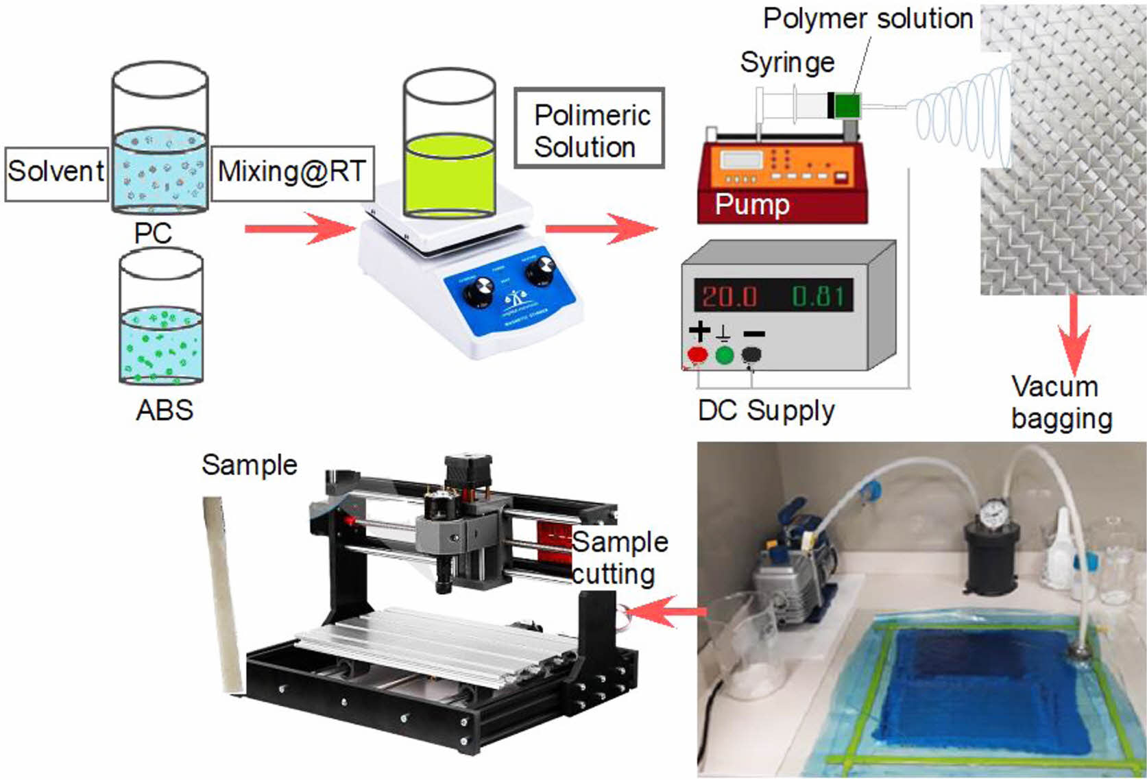
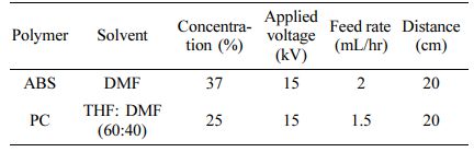
Electrospinning Process. Solvents tetrahydro-furan (THF) and N,N-dimethyl formamide (DMF) were used with ABS and PC to produce electrospun nano-fibers. ABS was dissolved in DMF with different concentrations of 22, 30 and 37 wt%, whereas PC was dissolved in a THF: DMF mixture of (60:40) with concentrations of 15, 20 and 25 wt%. Both solutions were mixed at room temperature for about 4-6 hours to ensure homogeneity. NE300 Multi Nozzle Electrospinning Machine (Inovenso Company, Türkiye) was utilized for the electrospinning process. Figure 1 shows the sequence followed throughout the study. The solution with varying concentrations was added to a syringe and then added to a syringe pump. With the help of high electrical energy applied, both ABS and PC polymeric solutions were converted into nanofibers by pumping with a syringe and sprayed on the glass fabric. In the next step, nanofiber-embedded glass fabrics were used in composite plate manufacturing. Lastly, mechanical test samples were obtained from composite plates and tests were carried out (Figure 1).
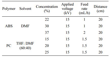
The syringe pump controlled the feed rates varying between 1-4 mL/h for ABS/DMF solutions and 1.5-3 mL/h for PC (60:40) THF: DMF solutions. For both solutions, a 21-gauge blunt needle was used. A distance of 20 cm was maintained between the tip of the nozzle and the ground collector. The ground collector was covered with aluminum foil to collect the nano-fibers. The applied high voltage varied between 15-18 kV. Table 1 shows the electrospinning parameters and concentrations studied during nanofiber production with respect to the ABS and PC polymers.
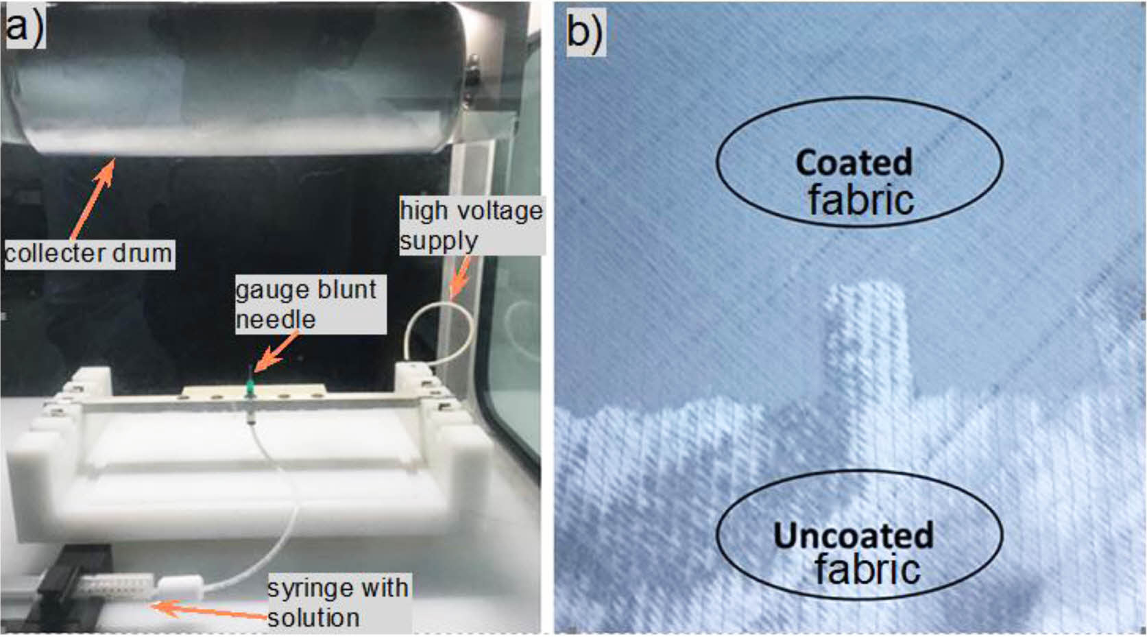
The production of nano-fibers was performed at room temperature and generally around 50-60 RH% with a vertical spinning configuration. Details and configuration of the electrospinning device can be seen in Figure 2.
With the optimum nano-fiber production parameters, both ABS and PC solutions were sprayed on each woven glass fiber for 10 and 30 minutes (Figure 2(b)). Characterization of electrospun nanofibers was done by scanning electron microscope (SEM) to view the morphology.
Composite Manufacturing. To produce nanofiber-embedded glass fiber-reinforced polymer (GFRP) composite plates by vacuum infusion technique; epoxy resin was vacuum infused with a total of six woven glass fabrics. After the vacuum infusion and curing process, glass-fiber reinforced epoxy with ABS/PC electrospun nano-fiber composite plates were obtained.
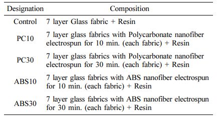
The first step is to clean the base glass very well via cellulosic thinner. Once the base is cleaned, polyvinyl alcohol (PVA) liquid mould release was poured and solidified. Seal tape is placed to ensure a strong vacuum. The hand lay-up process begins and once a total of 6 layers of fibers was placed with resin an infusion net and a nylon release film were used to cover and seal the resin and fibers. The vacuum pump was started and a high vacuum was maintained for at least 5 hours. After 5 hours the pump was stopped and the plate was let to cure for at least 24 hours. Mechanical tests such as tensile, flexural, and impact tests were planned to be performed on the composites to see the effect of electrospun ABS and PC fibers. Table 2 gives the compositions and designations of the composite materials studied.
Test and Characterization. The tensile behavior of the composite materials has been investigated with respect to ASTM D638-08. Tensile tests were conducted with Shimadzu AG-IS tensile testing machine with 5 mm/min crosshead speed at room temperature and 50% relative humidity. To understand the flexural properties, a three-point bending test was carried out according to the ASTM D790 standard. Test samples were tested using a Shimadzu testing device with a 3.14 mm min-1 rate of crosshead motion. Standard flexural strength was obtained by eq. (1).
where;
σf is flexural strength (MPa); P is the maximum load (N); L is support span length (mm); b is the width of the specimen (mm); d is the thickness of the specimen (mm).
Impact tests were performed according to EN ISO 179. Test specimens had the “type A” single notch and were tested by using Cometech QC6390 digital impact testing with a 7 J pendulum and 150° angle. Breaking energy was obtained and impact strength was calculated by eq. (2).

where, αcU is impact strength (kJ/m2); Ec (joules) is the absorbed energy by breaking, b (mm) is the width, and h (mm) is the thickness of the samples. At least five specimens were tested for each batch and the results were averaged arithmetically for all mechanical tests.
Tensile test sample samples dimensions, which were cut by a precision mini milling machine were supplied in lengths of 33 mm, in width of 6 mm and in thickness of 3.2 mm. Dimensions of the rectangular flexural test sample were 140 mm in length, 14 mm in width, and 3.2 mm in thickness. Rectangular impact samples had 63.5 mm in length, 3.2 mm in thickness and 13 mm in width.
Electron Microscopy Observation. Electron microscopy analysis was applied to investigate nano-size ABS and PC solutions in the glass fabrics. The electrospun mats were dried under vacuum at 60 °C for 2 h before the SEM observation. The whole electrospun fabrics were gold-coated by the sputtering device (Q 150, Netherland) to avoid electrostatic charging and to obtain clear images. Scanning electron microscope images were obtained using a JEOL, JCM-6000 device with 20 kV energy.
|
Figure 1 Schematic illustration of the study plan. |
|
Figure 2 (a) Configuration of Electrospinning Setup; (b) Woven Glass Fabric Coated and Uncoated with Electrospun PC nanofibers. |
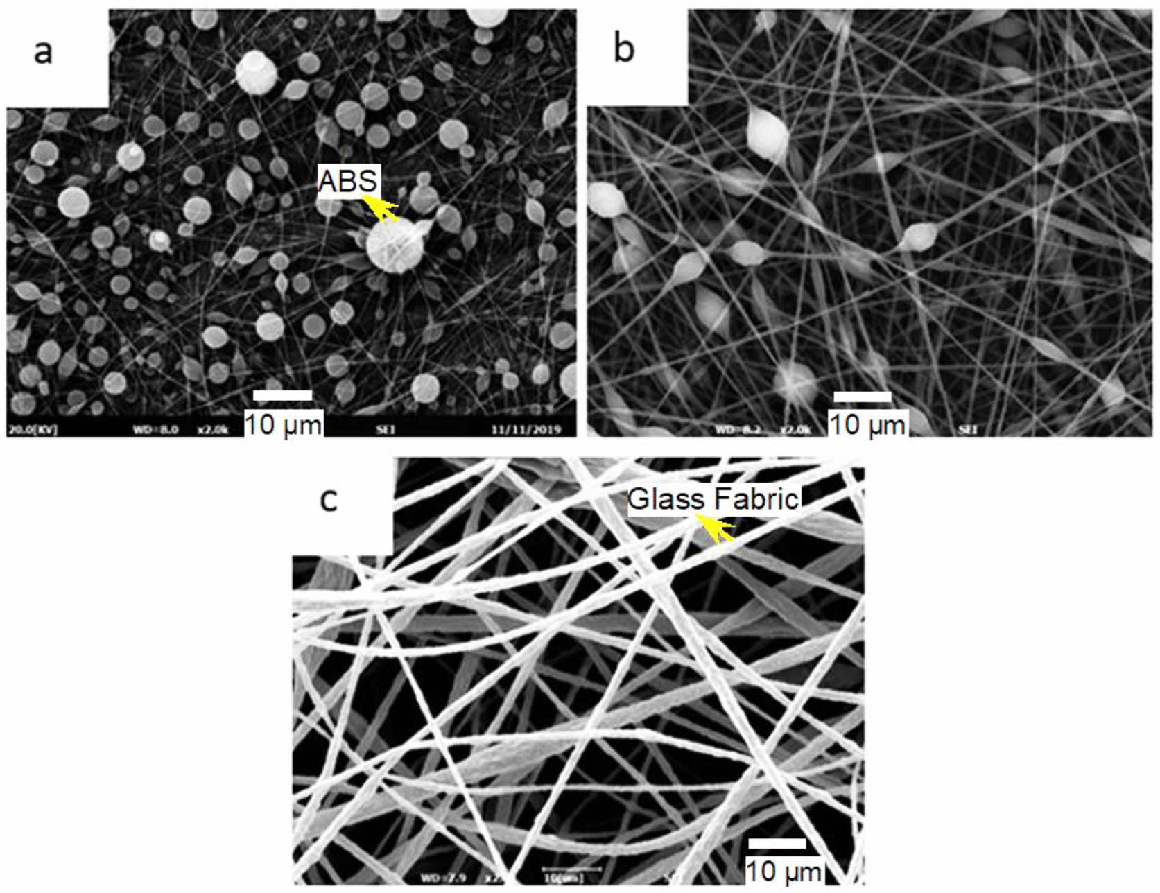
ABS and PC Nanofiber Production. The study began with the electrospinning of the ABS/DMF solution. Initially, nanofibers with relatively low concentrations of 22 wt% were prepared and the concentration was increased to 30 wt% and 37 wt% to achieve electrospun fibers without any beads. The parameters in Table 1 were used and the resulting structures are observed in Figure 3. As can be seen from Figure 3(a), 22 wt% ABS solution yields fibers however bead structures were also visible. To reduce the number of beads and achieve fine fibers the concentration of the ABS solution was gradually increased and the 30 wt% ABS solution electrospinning result can be seen in Figure 3(b). In order to produce fine, bead-free fibers, the concentration of ABS/DMF solution was increased up to 37 wt% and electrospun according to the parameters in Table 1. Figure 3(c) shows desired bead-free fiber SEM image which produced with ABS/DMF solution.
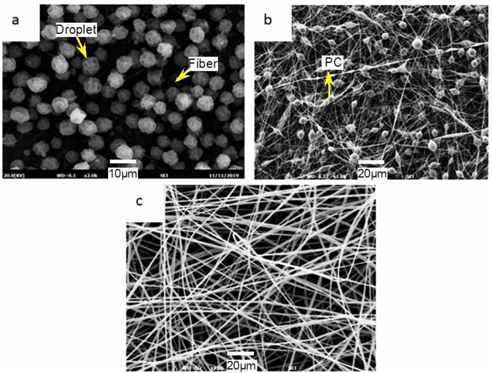
THF: DMF solution was used for PC pellets as a result of the fact that they were dissolved more quickly in THF than DMF. According to Shawon and Sung SEM and TEM studies,56 there were few bead flaws at lower solvent mixture ratios (THF: DMF at 60:40), but when the ratios were steadily increased (70:30, 80:20, 90:10, and neat THF), bead formation became more prevalent across fibers. Due to the increased vapor pressure of THF, more solvent evaporation occurred at larger ratios of THF and DMF solvent mixes and was assumed to evaporate right from the capillary tip. In spite of being lower vapor pressure of DMF, the rate of solvent evaporation from the fiber surface increased due to the large volume of THF in the polymer solution, causing the fibers to transport more charges per unit mass. Therefore, to obtain electrospun PC nanofibers, PC pellets were dissolved within a solvent mixture of (60:40) THF: DMF at different concentrations of 15, 20, and 25 wt% with the electrospinning parameters from Table 1. Samples from the electrospun PC nanofibers at different concentrations can be seen in Figure 4.
As seen in Figure 4(a), spherical structures with very little amounts of fibers are formed from the electrospinning process. It was clear that the solution concentration was too low as there was not enough surface tension for the jet to elongate and form fibers. Since the jet was not able to elongate, the spraying of spheres was observed. This paper believes the wrinkled structures of the spheres are due to the faster evaporation of the solvent on the outer layer compared to the core. Since 15 wt% PC concentrations did not result in enough surface tension of the jet, the concentration was increased to 20 wt% and the result can be seen in Figure 4(b). With the process parameters from Table 1, the 20 wt% PC solution yielded improved results compared to 15 wt%. The surface tension was enough for the jet to elongate and form fibers. Bead-like structures were also formed due to insufficient solution concentration and viscosity. Therefore, the solution concentration was increased from 20 to 25 wt%. As can be seen in Figure 4(c), the result of the electrospinning of 25 wt% PC solution yielded bead-free fibers. The parameters to manufacture these fibers were considered to be the best parameters and were used to coat the glass fabrics to be used in GFRP composites. Table 3 provides the best electrospinning parameters to produce ideal ABS and PC nanofibers. For the next step of the study, electrospun nanofibers were sprayed on the glass fabrics prior to the composite manufacturing.
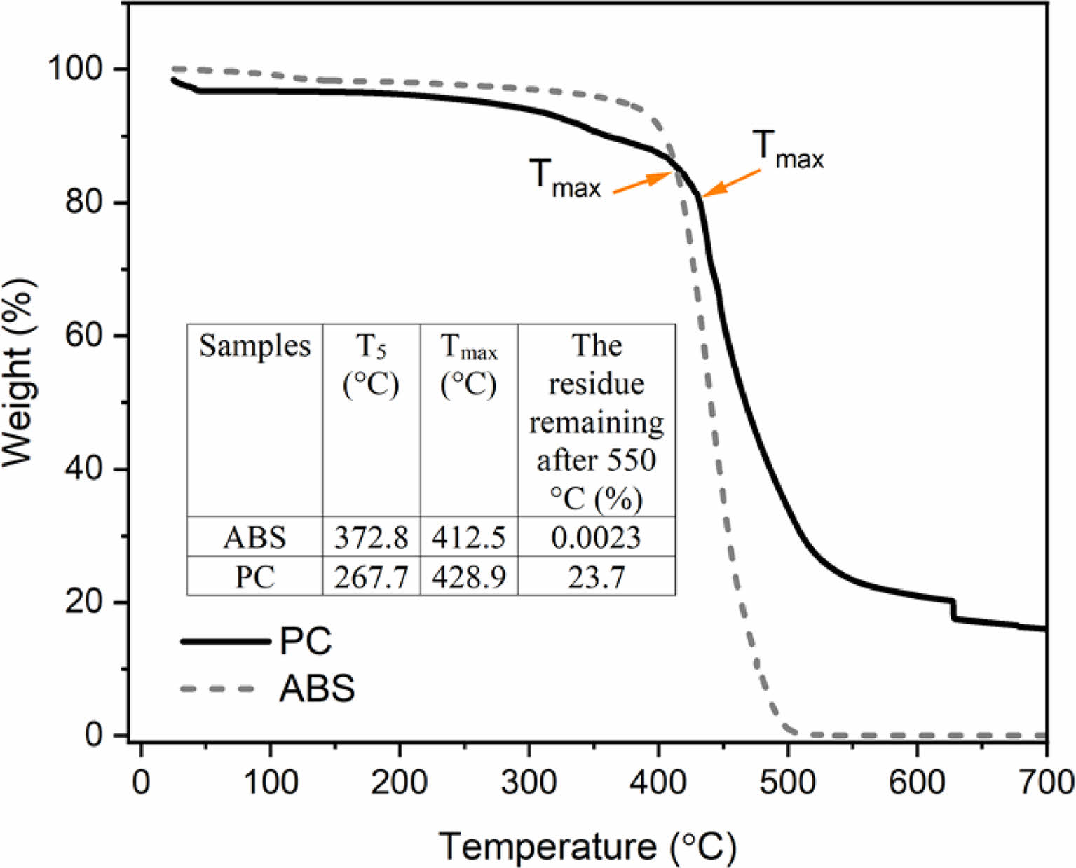
Thermal Analysis of ABS and PC Nanofibers. Thermogravimetric analyses (TGA) were also conducted to see whether the ABS and PC nanofibers which were embedded into the composites as a layer, would cause any thermal decomposition during the curing process of the polyester matrix. Because it is well known that different curing cycles can be applied at various temperatures and pressure values, depending on the resin type. Therefore, to avoid any unwanted thermal degradation, thermo gravimetric analysis was performed at a rate of 10 ℃/min until 700 ℃. TGA results can be seen in Figure 5. The fibers were electrospun according to the chosen optimum parameters and the fibers were placed into the TGA device for analysis with help of tweezers.
Figure 5 shows the initial degradation temperature (T5) corresponding to the temperature at 5 wt% mass loss specified as the beginning separation temperature, sample. As can be seen from Figure 5, thermal degradation begins at approximately 372 ℃ and 267 ℃ for the electrospun ABS and PC nanofibers respectively. The maximum decomposition temperature (Tmax) of the samples electrospun ABS and PC nanofibers were measured to be at around 412 ℃ and 429 ℃, respectively. Compared to electrospun PC nanofiber, the charring rate significantly improved electrospun ABS nanofiber after the 550 ℃ thermal degradation test.
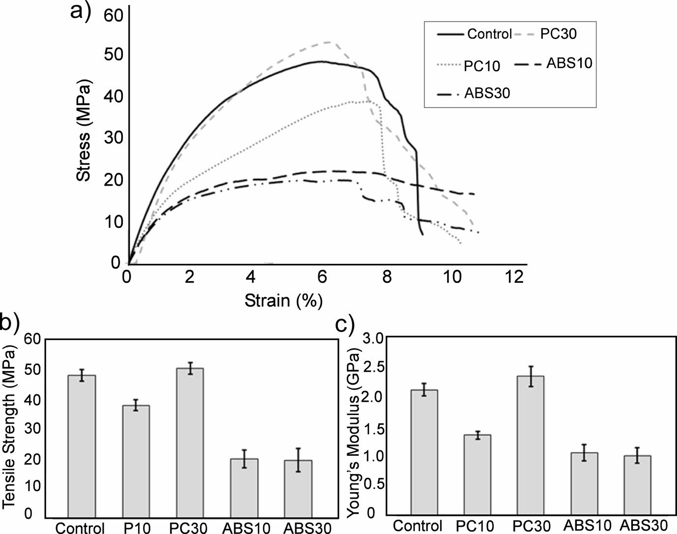
Mechanical Properties of ABS and PC Nanofiber-embedded GFRPs. In Figure 6, the tensile test results of composite samples are displayed. According to test results, the tensile strength (TS) of the GFRP sample which is called as control, showed a sharp decrease with the addition of ABS nanofibers from 48 MPa to around 20 MPa regardless of the ABS nanofiber content. This same trend of a decrease in TS was also seen for the PC10 samples, where a reduction of 38 MPa was recorded. On the contrary, when the electrospinning duration of the PC was increased to 30 minutes, an increase to 50 MPa was recorded. A similar trend in tensile strength can also be observed in Young’s modulus (YM) values (Figure 6). The YM of the control samples, which was approximately 2.1 GPa, was adversely affected for all composites except for the PC30 sample which has a YM of about 2.3 GPa. On the other hand, the YM of the PC10 sample and ABS nanofiber-reinforced composite samples were found to be approximately 1.3 GPa and 1 GPa, respectively. According to Moon and Farris,54 the best morphologically aligned electrospun PC fiber was created with a polymer concentration of 22%, a solvent ratio of 50:50 THF: DMF, a 14 kV applied voltage, a flow rate of 0.050 mL/m, and a take-up velocity of 7.3 m/s. The 22 percent PC fibers had an ultimate tensile strength of around 64 MPa.
In general, tensile test results showed that the embedding of ABS nanofiber in glass fabric for both 10 and 30 minutes was not efficient. On the other hand, considering the tensile properties, it was understood that the PC nanofiber should be embedded in the glass fabric for at least 30 minutes with the ideal electrospinning parameters obtained (feeding speed, voltage and distance between the needle tip and the collector) in order to have appreciable tensile properties.
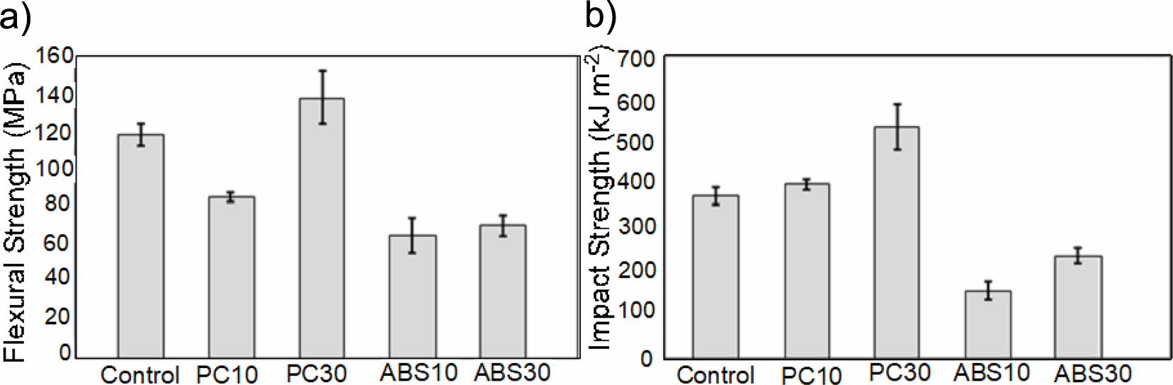
Figure 7 provides the variation of flexural and impact strength values of composite materials according to nanofiber and electrospinning time. As shown in Figure 7(a), the flexural strength of the control sample without nanofibers was measured as 118 MPa. As a function of the nanofiber content and coating time, the flexural strength of control was found to display similar trends as the tensile properties. Flexural tests showed that the control composite decreased from 118 MPa to around 60-70 MPa with the addition of ABS nanofiber regardless of the electrospinning time. The reduction in tensile and flexural strength with the incorporation of ABS nanofibers to control is probably due to the hydrophobic character of ABS that hardens the wettability of glass fabrics resulting in poor interfacial adhesion between reinforcement and resin. Authors also believe that low porosity between ABS nanofibers might be another reason for the drop in tensile and flexural properties that hinders the resin motility and weakens the interface. In addition, flexural strength values of PC 10 composite samples were found 28% lower compared to those of control samples. On the other hand, a flexural strength of 138 MPa (16% higher than the control sample) was found for the PC30 composite samples which were formed by spraying the PC nanofibers on glass fabrics for 30 minutes. Hassan et al.57 investigated the effect of PC content on the mechanical properties of ABS/PC blends. Similar to these results, they have found that increasing the PC content in ABS/PC blends caused a remarkable increment in flexural and impact strength and reached the highest values of 75 MPa and 73 kJ/m2 respectively which are still lower than those of neat PC.
In Figure 7(b), the impact strength values of composite materials are given. Although the changes in the impact strength of the control containing ABS nanofibers were similar to the changes in the tensile and bending properties, significant improvements were observed in the control samples containing PC nanofibers. According to the impact test results, the impact strength of the control samples was measured to be 374 kJ/m2 and was increased up to 400 kJ/m2 for PC10 composite samples. Furthermore, it was observed that the impact resistance properties of the control composite were further enhanced as the PC electrospinning duration increased. The impact strength of the control sample increased by approximately 42%, reaching a value of 534 kJ/m2 with the embedded PC30 fibers. On the other hand, the impact strength values of control composite samples containing ABS nanofibers were found to be around 153 kJ/m2 and 236 kJ/m2 for ABS 10 and ABS 30 composites, respectively.
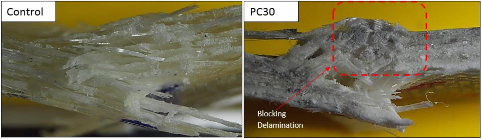
To support the results of the impact test, the fracture surfaces of the samples were examined with an optical microscope after the test. Figure 8 shows the fracture surfaces of the control sample without nanofibers and the PC30, sample which has the highest mechanical properties. As seen in Figure 8, the nanofiber layers in the PC30 test sample reduced the delamination between the layers caused by the impact load. On the other hand, delamination between the layers in the control sample was observed much more compared to the PC30 sample after the impact load. Therefore, the increase of approximately 42% in impact strength may be attributed to this fact.
|
Figure 3 The resulting structure of the electrospinning process at different concentrations: (a) 22 wt% ABS; (b) 30 wt% ABS; (c) 37 wt% ABS solution concentrations. |
|
Figure 4 Electrospinning result of (a) 15 wt%; (b) 20 wt%; (c) 25 wt% PC Solution. |
|
Figure 5 TGA of ABS and PC nanofibers. |

|
Figure 6 Tensile behavior of composite samples: (a) stress-strain curves; (b) tensile strength; (c) Young’s modulus |
|
Figure 7 (a) Flexural; (b) impact properties of composite samples |
|
Figure 8 Optical images of test samples fracture surface after impact test. |
To produce bead-free ABS and PC nanofibers, the electrospinning parameters were studied and the best parameters were obtained. It is clear that as the polymeric concentration increased, the bead density decreased. Since the embedded fibers are electrospun in the nanometer size, TGA tests were performed to observe if any thermal degradation of the polymers occurs during the cure cycle. The results show that this is not the case since ABS and PC have high thermal degradation temperature values. Mechanical tests showed that incorporating ABS nanofibers into the composite structure has no positive effect on the mechanical properties of control regardless of the electrospinning duration. On the contrary, the effect of PC nanofibers on the mechanical properties was found to be highly dependent on the electrospinning spray time. Although tensile and flexural properties remain almost unchanged, the incorporation of PC nanofibers with a 30-minute spraying duration enhanced the impact properties of the control sample to around 40%.
- 1. Canturri, C.; Greenhalgh, E. S.; Pinho, S. T.; Ankersen, J. Delamination Growth Directionality and the Subsequent Migration Processes–The Key to Damage Tolerant Design. Composites Part A 2013, 54, 79-87.
-

- 2. Bull, D. J.; Scott, A. E.; Spearing, S. M.; Sinclair, I. The Influence of Toughening-Particles in CFRPs on Low Velocity Impact Damage Resistance Performance. Composites Part A 2014, 58, 47-55.
-
- 3. Quan, D.; Ivankovic, A. Effect of Core–Shell Rubber (CSR) Nano-Particles on Mechanical Properties and Fracture Toughness of an Epoxy Polymer. Polymer 2015, 66, 16-28.
-
- 4. Ngah, S. A.; Taylor, A. C. Toughening Performance of Glass Fibre Composites with Core–Shell Rubber and Silica Nanoparticle Modified Matrices. Composites Part A. 2016, 80, 292-303.
-
- 5. Chikhi, N.; Fellahi, S.; Bakar, M. Modification of Epoxy Resin Using Reactive Liquid (ATBN) Rubber. Eur. Polym. J. 2002, 38, 251-264.
-
- 6. Dadfar, M. R.; Ghadami, F. Effect of Rubber Modification on Fracture Toughness Properties of Glass Reinforced Hot Cured Epoxy Composites. Mater. Design. 2013, 47, 16-20.
-
- 7. Nash, N. H.; Young, T. M.; McGrail, P. T.; Stanley, W. F. Inclusion of a Thermoplastic Phase to Improve Impact and Post-impact Performances of Carbon Fibre Reinforced Thermosetting Composites—A Review. Mater. Design. 2015, 85, 582-597.
-
- 8. Huang, Y.; Kinloch, A. J. Modelling of the Toughening Mechanisms in Rubber-modified Epoxy Polymers. J. Mater. Sci. 1992, 27, 2753-2762.
-
- 9. Chandrasekaran, S.; Sato, N.; Tölle, F.; Mülhaupt, R.; Fiedler, B.; Schulte, K. Fracture Toughness and Failure Mechanism of Graphene-Based Epoxy Composites. Key Eng. Mater. 2014, 97, 90-99.
-
- 10. Park, Y. T.; Qian, Y.; Chan. C.; Suh, T.; Nejhad, M. G.; Macosko, C.; Stein, A. Epoxy Toughening with Low Graphene Loading. Adv. Funct. Mater. 2015, 25, 575-585.
-
- 11. Al‑Dhahebib, A. M.; Gopinath, S. C. B.; Saheed, M. S. M. Graphene Impregnated Electrospun Nanofiber Sensing Materials: A Comprehensive Overview on Bridging Laboratory Set-up to Industry. Nano Convergence 2020, 7, 1-23.
-
- 12. Gojny, F. H.; Wichmann, M. H. G.; Köpke, U.; Fiedler, B.; Schulte, K. Carbon Nanotube-reinforced Epoxy-composites: Enhanced Stiffness and Fracture Toughness at Low Nanotube Content. Key Eng. Mater. 2004, 64, 2363-2371.
-
- 13. Sprenger, S. Improving Mechanical Properties of Fibre-reinforced Composites Based on Epoxy Resins Containing Industrial Surface-modified Silica Nanoparticles: Review and Outlook. J. Compos. Mater. 2015, 49, 53-63.
-
- 14. Peng, M.; Zhou, Y.; Zhou, G.; Yao, H. Triglycidyl Para-aminophenol Modified Montmorillonites for Epoxy Nanocomposites and Multi-scale Carbon Fibrereinforced Composites with Superior Mechanical Properties. Key Eng. Mater. 2017, 148, 80-88.
-
- 15. Wang, J.; Xu, J.; He, Y. Novel Smart Textile with Ultraviolet Shielding and Thermo-regulation Fabricated via Electrospinning. J. Energ. Storagt. 2021, 42, 103094.
-
- 16. Shao, W.; He, J.; Han Q.; Sang, F.; Wang, Q.; Chen, L.; Ding, B. A Biomimetic Multilayer Nanofibre Fabric Fabricated by Electrospinning and Textile Technology from Polylactic Acid and Tussah Silk Fibroin as a Scaffold for Bone Tissue Engineering. Mater. Sci. Eng.2016, 67, 599-610.
-
- 17. Uddin, F.; Ahmad, T.; Ullan, Y.; Nawab, S.; Ahmad, F.; Azam, A.; Rasheed, M. S. Recent Trends in Water Purification Using Electrospun Nanofibrous Membranes. Inter J. Environ. Sci. Technol. 2021, 498, 2448-2455.
-
- 18. Wang, D. H.; Su, J.; Liu, Y. M.; Yu, Y.; Su, Y.; Xie, G. X.; Jiang, L. L.; Zhou, L. N.; Zhu, D. Y.; Chen, S. H.; Yan, J.; Wang, X. X.; Long, Y. Z. Recent Advances in Electrospun Magnetic Nanofibers and Their Applications. J. Mater. Chem. C 2022, 10, 4072-4095.
-
- 19. Lu, Y.; Xiao, X.; Liu, Y.; Wang, J.; Qi, S.; Huan, C.; Liu, H.; Zhu, Y.; Xu, G. Achieving Multifunctional Smart Textile with Long Afterglow and Thermo-regulation via Coaxial Electrospinning. J. Alloys Compounds 2020, 812, 152144.
-
- 20. Kenawy, E. R.; Abdel-Hay, F. I.; El-Newehy, M. H.; Wnek, G. E. Processing of Polymer Nanofibres Through Electrospinning as Drug Delivery Systems. In Nanomaterials: Risks and Benefits; Dordrecht: Springer, 2009.
-
- 21. Sill, T. J.; Recum, H. A. Electrospinning: Applications in Drug Delivery and Tissue Engineering. Biomaterials 2008, 29, 1989-2006.
-
- 22. Do, G. L.; Gyeong, B. R.; Jung, K.-H. Energy Storage Performance of Carbon Nanofiber Electrodes Derived from Crosslinked PI/PVDF Blends. Polym. Korea 2021, 45, 927-933.
-
- 23. Hu, X.; Liu, S.; Zhou, G.; Huang, Y.; Xie, Z; Jing, X. Electro- spinning of Polymeric Nanofibres for Drug Delivery Applications. J. Control. Release 2014, 185, 12-21.
-
- 24. Agarwal, S.; Wendorff, J. H.; Greiner, A. Progress in the Field of Electrospinning for Tissue Engineering Applications. Adv. Mater. 2009, 21, 3343-3351.
-
- 25. Younghan, S.; Yujeong K.; Hyungsup, K. Effect of Crystallinity and Thermal Stability of Nanostructured Cellulose/Halloysite Nanotube Composites. Polym. Korea 2019, 43, 958-964.
-
- 26. Bosworth, L.; Downes, S. Electrospinning for Tissue Regeneration. Amsterdam: Elsevier, 2011.
- 27. Ahmed, F. E.; Lalia, B. S.; Hashaikeh, R. A Review on Electrospinning for Membrane Fabrication: Challenges and Applications. Desalination 2015, 356, 15-30.
-
- 28. Liu, H.; Hsieh, Y. L. Ultrafine Fibrous Cellulose Membranes from Electrospinning of Cellulose Acetate. J. Polym. Sci. Pol. Phys. 2002, 40, 2119-2129.
-
- 29. Wu, L.; Yuan, X.; Sheng, J. Immobilization of Cellulase in Nanofibrous PVA Membranes by Electrospinning. J. Membrane Sci. 2005, 250, 167-173.
-
- 30. Kim, J. S.; Reneker, D. H. Mechanical Properties of Composites Using Ultrafine Electrospunfibres. Polym. Composit. 1999, 20, 124-131.
-
- 31. Akangah, P.; Shivakumar, K. Assessment of Impact Damage Resistance and Tolerance of Polymer Nanofibre Interleaved Composite Laminates. J. Chem. Sci. Technol. 2013, 2, 39-52.
- 32. Akangah, P. Lingaiah, S. Shivakumar, K. Effect of Nylon-66 Nano-fibre Interleaving on Impact Damage Resistance of Epoxy/Carbon Fibre Composite Laminates. Compos. Struct. 2010, 92, 1432-1439.
-
- 33. Zarei, H.; Brugo, T.; Belcari, J.; Bisadi, H.; Minak, G.; Zucchelli, A. Low Velocity Impact Damage Assessment of GLARE Fibre-metal Laminates Interleaved by Nylon 6, 6 Nanofibre Mats. Compos. Struct. 2017, 167, 123-131.
-
- 34. Anand, A.; Kumar, N.; Harshe, R.; Joshi, M. Glass/epoxy Structural Composites with Interleaved Nylon 6/6 Nanofibres. J. Compos. Mater.2017, 51, 3291-3298.
-
- 35. Giuliese, G.; Palazzetti, R.; Moroni, F.; Zucchelli, A.; Pirondi, A.; Minak, G.; Ramakrishna, S. Experimental and Numerical Study of the Effect of Nylon 6, 6 Electrospun Nanofibrous Mats on the Delamination of CFR-epoxy Composite Laminates. 19th International Conference on Composite Materials 2013, Montreal, Canada, July 28-Aug 2, 2013, Curran Associates Inc.: New York, 2013.
-
- 36. Romo-Uribe, A.; Arizmendi, L.; Romero-Guzmán, M. E.; Sepulveda-Guzmán, S.; Cruz-Silva, R. Electrospun Nylon Nanofibres as Effective Reinforcement to polyaniline Membranes. ACS Appl. Mater. Inter.2009, 1, 2502-2508.
-
- 37. Chen, L. S.; Huang, Z. M.; Dong, G. H.; He, C. L.; Liu, L.; Hu, Y. Y.; Li, Y. Development of a Transparent PMMA Composite Reinforced with Nanofibres. Polym. Compos. 2009, 30, 239-247.
-
- 38. Neppalli, R.; Marega, C.; Marigo, A.; Bajgai, M. P.; Kim, H. Y.; Causin, V. Poly(ε-caprolactone) Filled with Electrospun Nylon Fibres: A Model for a Facile Composite Fabrication. Eur. Polym. J. 2010, 46, 968-976.
-
- 39. Chen, B.; Cai, H.; Mao, C.; Gan, Y.; Wei, Y. Toughening and Rapid Self-healing for Carbon Fiber/Epoxy Composites Based on Electrospinning Thermoplastic Polyamide Nanofiber. J. Polym. Compos. 2022, 43, 3124-3135.
-
- 40. Wu, X. F.; Yarin, A. L. Recent Progress in Interfacial Toughening and Damage Self-healing of Polymer Composites Based on Electrospun and Solution-blown Nanofibres: An Overview. J. Appl. Polym. Sci. 2013, 129, 2225-2237.
-
- 41. Seongpil, A.; Liou, M.; Song, K. Y.; Jo, H. S.; Lee, M. W.; Al-Deyab, S. S.; Yarin, A. L.; Yoon, S. S. Highly Flexible Transparent Self-healing Composite Based on Electrospuncoreshellnanofibres Produced by Coaxial Electrospinning for Anti-corrosion and Electrical Insulation. Nanoscale 2015, 7, 17778-17785.
-
- 42. Nissilä, T.; Hietala, M.; Oksman, K. A Method for Preparing Epoxy-cellulose Nanofibre Composites with an oriented Structure. Composites Part A 2019, 125, 105515.
-
- 43. Schmatz, D. A.; Costa, J. A. V.; Morais, M. G. A Novel Nanocomposite for Food Packaging Developed by Electrospinning and Electrospraying. Food Packaging Shelf 2019, 2, 100314.
-
- 44. Wu, H.; Chen, Y.; Chen, Q. Ding, Y.; Zhou, X.; Gao, H. Synthesis of Flexible Aerogel Composites Reinforced with Electrospun Nanofibres and Microparticles for Thermal Insulation. J. Nanomater 2013, 375093.
-
- 45. Bahi, A.; Shao, J.; Mohseni, M.; Ko, F. K. Membranes Based on Electrospun Lignin-zeolite Composite Nanofibres. Sep. Purif. Technol. 2017, 187, 207-213.
-
- 46. Neisiany, R. E.; Khorasani, S. N.; Lee, J. K. Y.; Naeimirad, M.; Ramakrishna, S. Interfacial Toughening of Carbon/Epoxy Composite by Incorporating Styrene Acrylonitrile Nanofibres. Theor. Appl. Fract. Mec. 2018, 95, 242-247.
-
- 47. Calderon, A.; Que, M. C.; Premacio, A.; Marasigan, D. Morphological Characterization of Electrospun Zeolite-filled Acrylonitrile Butadiene Styrene Fibrous Membrane for Lowpressured CO2 Adsorption. Sustain. Environ. Res. 2014, 24, 365-371.
- 48. Chiu, Y. J.; Chi, M. H.; Liu, Y. H.; Chen, J. T. Fabrication, Morphology Control, and Electroless Metal Deposition of Electrospun ABS Fibres. Macromol. Mater. Eng. 2016, 301, 895-901.
-
- 49. Zulfi, A.; Hapidin, D. A.; Munir, M. M.; Iskandar, F.; Khairurrijal, K. The Synthesis of Nanofibre Membranes from Acrylonitrile Butadiene Styrene (ABS) Waste Using Electrospinning for Use as Air Filtration Media. RSC Adv. 2019, 9, 30741-30751.
-
- 50. Charde, S. J.; Sonawane, S. S.; Sonawane, S. H.; Navin, S. Influence of Functionalized Calcium Carbonate Nanofillers on the Properties of Melt-extruded Polycarbonate Composites. Chem. Eng. Commun. 2018, 205, 492-505.
-
- 51. Baby, T.; George, G.; Varkey, V.; Cherian, S. K. A New Approach for the Shaping up of Very Fine and Bead-free UV Light Absorbing Polycarbonate Fibres by Electrospinning. Polym. Test. 2019, 80, 106103.
-
- 52. Krishnappa, R. V. N.; Desai, K.; Sung, C. Morphological Study of Electrospun Polycarbonates as a Function of the Solvent and Processing Voltage. J. Mater. Sci. 2003, 38, 2357-2365.
- 53. Shawon, J.; Sung, C. Electrospinning of Polycarbonate Nanofibres with Solvent Mixtures THF and DMF. J. Mater. Sci. 2004, 39, 4605-4613.
-
- 54. Moon, S.; Farris, R. J. The Morphology, Mechanical Properties, and Flammability of Aligned Electrospun Polycarbonate (PC) Nanofibres. Polym. Eng. Sci. 2008, 48, 1848-1854.
-
- 55. Sihn, S.; Kim, R. Y.; Huh, W.; Lee, K. H.; Roy, A. K. Improvement of Damage Resistance in Laminated Composites with Electrospun Nano-interlayers. Compos. Sci. Technol. 2008, 68, 673-683.
-
- 56. Shawon, J.; Sung, C. Electrospinning of Polycarbonate Nanofibres with Solvent Mixtures THF and DMF. J. Mater. Sci. 2004, 39, 4605-4613.
-
- 57. Hassan, A.; Wong, Y. J. Mechanical Properties of High Impact ABS/PC Blends-Effect of Blend Ratio. Simposium Polimer Kebangsaan Ke-V, Selangeor, Malaysia, Aug 23-24, 2005.
- Polymer(Korea) 폴리머
- Frequency : Bimonthly(odd)
ISSN 0379-153X(Print)
ISSN 2234-8077(Online)
Abbr. Polym. Korea - 2022 Impact Factor : 0.4
- Indexed in SCIE
 This Article
-
2023; 47(2): 117-126
Published online Mar 25, 2023
- 10.7317/pk.2023.47.2.117
- Received on Sep 29, 2022
- Revised on Nov 28, 2022
- Accepted on Dec 20, 2022
Services
- Full Text PDF
- Abstract
- ToC
- Conflict of Interest
Introduction
Experimental
Results and Discussion
Conclusions
- References
Shared
Correspondence to
- Ali Avci
-
Faculty of Engineering, Hakkari University, Hakkari 30000, Türkiye
- E-mail: aliavci@hakkari.edu.tr
- ORCID:
0000-0003-3901-6248
Hyecheon Building(Room 601), #354, Gangnam-Daero, Gangnam-Gu, Seoul 06242, Korea
TEL : 82-2-568-3860, 561-5203, 569-3860 FAX : 82-2553-6938 E-mail: polymer@polymer.or.kr